
What Is a Fluoroscopy System? Real-Time Imaging Technology and Medical Uses
The fluoroscopy system is one of the most versatile and widely deployed imaging platforms in modern clinical medicine, enabling real-time X-ray visualization that powers everything from gastrointestinal diagnostics to complex cardiac interventions and intraoperative orthopedic guidance. For biomedical engineers, understanding the physics, engineering architecture, regulatory landscape, and maintenance demands of fluoroscopy systems is essential—these devices represent a high-risk, high-value intersection of radiation physics, detector technology, image processing, and interventional medicine. This article provides a comprehensive technical overview of the fluoroscopy system, from its historical origins to the latest AI-driven innovations reshaping how it delivers care.
Table of Contents
- What is a Fluoroscopy System?
- Why is a Fluoroscopy System Used?
- How Does a Fluoroscopy System Work in General?
- What Are the Main Components of a Fluoroscopy System?
- What Types/Variants of Fluoroscopy Systems Exist?
- What Are the Main Benefits of a Fluoroscopy System?
- What Are the General Risks or Limitations?
- How Is the Fluoroscopy System Evolving / Recent Innovations?
- Key Takeaways / Tips for Biomedical Engineers
1. What is a Fluoroscopy System?
Definition and Clinical Significance
A fluoroscopy system is a specialized X-ray imaging modality that produces continuous, real-time video-like images of internal body structures. Unlike conventional static radiography, which captures a single still image, fluoroscopy allows clinicians to observe dynamic physiological processes—such as the movement of contrast agents through blood vessels, the passage of barium through the gastrointestinal tract, or the real-time positioning of a catheter or surgical instrument. This live imaging capability makes fluoroscopy an indispensable tool across numerous medical specialties, from interventional radiology and cardiology to gastroenterology and orthopedics. As part of the broader family of radiological devices, fluoroscopy systems occupy a unique position by bridging diagnostic imaging and minimally invasive therapeutic procedures.

History and Evolution
The concept of fluoroscopy dates back to the very earliest days of X-ray science. Shortly after Wilhelm Conrad Röntgen’s discovery of X-rays in 1895, Thomas Edison developed the fluoroscope in 1896—a device consisting of a fluorescent calcium tungstate screen that glowed when struck by X-rays, allowing practitioners to observe internal structures in real time. These early systems, however, produced dim images and required total room darkness, and operators received no radiation protection whatsoever. The mid-20th century saw a transformative advance with the introduction of the X-ray image intensifier tube (XRII) in the 1950s, which amplified image brightness by a factor of 1,000 or more, enabling well-lit room examinations and television camera coupling for remote viewing. From the 1990s onward, flat-panel detectors (FPDs) began replacing XRIIs, offering superior image quality, reduced patient dose, wider dynamic range, and direct digital output compatible with modern picture archiving systems (PACS).
How Fluoroscopy Differs from Static X-Ray Imaging
While both fluoroscopy and conventional radiography rely on X-ray attenuation through tissues, the key distinction lies in temporal resolution and X-ray delivery. A standard X-ray delivers a brief, high-intensity pulse to capture one frozen image. Fluoroscopy, by contrast, delivers a continuous or rapidly pulsed X-ray beam—typically at frame rates of 7.5 to 30 frames per second—and processes each frame in real time for live display. This temporal capability allows physicians to track motion, guide instruments, and assess function rather than merely anatomy. The trade-off is higher cumulative radiation dose compared to a single radiograph, necessitating strict radiation management protocols.
2. Why is a Fluoroscopy System Used?
Gastrointestinal Imaging
One of the oldest and most common applications of fluoroscopy is gastrointestinal (GI) imaging. Barium swallow studies assess esophageal motility, swallowing dysfunction, and structural abnormalities such as strictures or hiatal hernias. Barium enema examinations evaluate the colon for polyps, diverticulosis, and inflammatory bowel disease. The real-time nature of fluoroscopy allows radiologists to observe peristalsis, valve function, and reflux phenomena that simply cannot be captured on static films.
Cardiovascular and Interventional Radiology
Fluoroscopy is the cornerstone of cardiac catheterization laboratories, enabling coronary angiography, percutaneous coronary intervention (PCI), stent placement, and electrophysiology studies. In interventional radiology, it guides catheter-based procedures including angioplasty, embolization, transjugular intrahepatic portosystemic shunt (TIPS) placement, and central venous catheter positioning. The live imaging ensures precise delivery of devices to target anatomy, reducing the risk of vascular injury. Biomedical engineers working in cardiac device development should also review cardiovascular devices to understand the broader device ecosystem in which fluoroscopy operates.
Orthopedics and Surgery
In orthopedic surgery, mobile C-arm fluoroscopy systems provide real-time guidance for fracture reduction, intramedullary nail placement, spinal pedicle screw insertion, and joint replacement positioning. Surgeons rely on live X-ray feedback to confirm correct implant positioning and alignment without exposing the patient to a full CT scan. This intraoperative role has made the mobile C-arm one of the most widely deployed fluoroscopic configurations in hospitals worldwide.
Comparison with Alternative Modalities
CT and MRI offer superior soft-tissue contrast and cross-sectional detail but are poorly suited for real-time procedural guidance due to scanner bore constraints, cost, and acquisition time. Ultrasound provides real-time imaging without radiation but lacks the penetration depth and detail required for bony structures and vascular road-mapping. Fluoroscopy uniquely combines real-time visualization, adequate spatial resolution for catheter-scale structures, and the ability to image the entire body with contrast enhancement, making it irreplaceable for dynamic procedural guidance.
3. How Does a Fluoroscopy System Work in General?
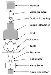
Schematic Diagram of a fluoroscopic system using an X-ray image intensifier (XRII) and video camera
X-Ray Generation and Beam Formation
X-rays in a fluoroscopy system are generated in an evacuated glass or metal-ceramic X-ray tube. A tungsten cathode filament is resistively heated, liberating electrons by thermionic emission. A high-voltage potential—typically 60 to 120 kVp in fluoroscopy—accelerates these electrons across the evacuated gap toward a rotating tungsten-rhenium anode disk, which spins at 3,000–10,000 RPM to distribute heat. The kinetic energy of electrons is converted to X-rays (via bremsstrahlung and characteristic radiation) and heat (>99%) at the anode focal spot, which ranges from 0.3 mm (high resolution, small field) to 1.2 mm (high power, large field). Aluminum and copper filters remove low-energy X-rays that would otherwise be absorbed by the patient without contributing to the image, thereby reducing skin dose.
Image Formation Chain
After passing through the patient, the attenuated X-ray beam strikes the image receptor. In legacy image intensifier systems (XRII), the input phosphor (cesium iodide, CsI) converts X-rays to light photons; a photocathode converts those to electrons; electrostatic electron optics focus and accelerate the electrons to an output phosphor approximately 1,000 times brighter and geometrically minified. In modern flat-panel detector (FPD) systems, a CsI scintillator converts X-rays to visible light, which is captured by an amorphous silicon (a-Si) thin-film transistor (TFT) photodiode array. Each pixel is read out electronically at frame rates of 15–30 fps, yielding direct digital images with consistent quality across the field of view.
Pulsed vs. Continuous Fluoroscopy
Continuous fluoroscopy delivers an uninterrupted X-ray beam and was the original operating mode. Modern systems predominantly use pulsed fluoroscopy, which fires brief X-ray pulses synchronized to the detector frame readout—typically at 7.5, 15, or 30 pulses per second. Between pulses, the last acquired frame is “frozen” on the display (last-image-hold feature), allowing physicians to study anatomy without ongoing radiation. Pulsed fluoroscopy reduces patient dose by 50–70% compared to continuous operation at equivalent clinical frame rates.
Automatic Dose Rate Control (ADRC)
Fluoroscopy systems incorporate Automatic Dose Rate Control (ADRC)—also called Automatic Exposure Control (AEC) or Automatic Brightness Control (ABC)—which continuously adjusts kVp, mA, pulse width, and added filtration to maintain a constant image brightness at the detector, regardless of patient size or tissue thickness. This ensures diagnostic image quality across varying patient anatomies while preventing both underexposure and unnecessary dose escalation. Biomedical engineers should understand that ADRC tuning parameters significantly influence the dose–image quality trade-off and require careful optimization during acceptance testing.
4. What Are the Main Components of a Fluoroscopy System?

The main components of Fluoroscopy system
X-Ray Tube and High-Voltage Generator
The X-ray tube is the primary radiation source and is housed in an oil-filled, lead-shielded tube housing to absorb off-focal radiation and heat. The rotating anode assembly—including the anode disk, bearing assembly, and stator/rotor motor—is a critical mechanical component requiring regular maintenance. The high-voltage (HV) generator supplies the kVp and mA settings to the tube. Modern generators are high-frequency inverter-based systems (operating at 40–100 kHz), which produce a nearly constant DC high voltage for stable output and lower ripple compared to older single- or three-phase designs. Generator power ratings for fluoroscopy typically range from 40 kW to 100 kW for angiography suites.
Beam Filtration and Collimation
Filtration consists of inherent filtration (X-ray tube glass/window, typically equivalent to 0.5–1.5 mm Al) plus added filtration (aluminum, copper, or rare-earth filters). Total filtration must meet regulatory minimums (typically 2.5 mm Al equivalent at 80 kVp, per IEC 60601-2-54). The beam collimator uses lead shutters to restrict the X-ray field to the clinical region of interest, reducing both scatter radiation and patient dose. Automatic collimation adjusts field size to match the selected field of view (FOV) on the detector.
Image Receptor: XRII vs. Flat-Panel Detector
The image receptor is the heart of the fluoroscopy system. X-ray image intensifiers (XRIIs) remain in service in older installations: they offer high temporal resolution but suffer from pincushion and vignette distortion, limited dynamic range, and geometric minification artifacts. Flat-panel detectors (FPDs) have become the standard in new installations. Indirect FPDs use a CsI(Tl) columnar crystal scintillator deposited directly on the TFT array, providing excellent spatial resolution (pixel pitch 150–200 µm), wide dynamic range (>10,000:1), and distortion-free imaging. Direct-conversion FPDs using amorphous selenium (a-Se) photoconductors are also available for higher intrinsic resolution applications.
Anti-Scatter Grid, Image Processor, and Display
An anti-scatter grid—consisting of thin lead septa separated by interspace material—is positioned between the patient and detector to absorb oblique scattered X-rays that would otherwise degrade contrast. Grid ratios of 8:1 to 12:1 are typical for fluoroscopy. The image processor performs real-time digital processing including noise reduction, edge enhancement, frame averaging, and digital subtraction angiography (DSA) algorithms. High-resolution flat-screen monitors (typically 2048×2048 or 2560×2048 pixels, calibrated to DICOM GSDF) provide the clinical display. Ergonomic control interfaces (foot pedals, touchscreen panels) allow hands-free operation during procedures.
C-Arm Gantry and Patient Table
The mechanical system holding the X-ray tube and detector in precise geometric alignment is the gantry. For fixed angiography suites, ceiling- or floor-mounted isocentric C-arm gantries provide rotation around the patient isocenter with precise angulation control (LAO/RAO, cranial/caudal). The carbon fiber patient table allows full X-ray transparency, motorized positioning (five or six degrees of freedom), and maximum weight capacity (typically 200–300 kg). Bi-plane systems incorporate two perpendicular C-arm assemblies for simultaneous two-plane imaging, critical in neurointerventional and pediatric cardiology applications.
5. What Types/Variants of Fluoroscopy Systems Exist?
Overview of Major Types
Fluoroscopy systems are manufactured in a variety of configurations tailored to specific clinical environments and procedural requirements. From portable battery-powered mini C-arms used in hand surgery clinics to large fixed bi-plane systems installed in dedicated neurointervention suites, the range of equipment is broad. Below is a summary of the major system types currently in clinical use, followed by a detailed comparison table.
| Type | Description | Key Features | Dose Level | Typical Clinical Use |
|---|---|---|---|---|
| Conventional Fixed-Room (XRII) | Stationary room-based system with image intensifier tube | Continuous/pulsed modes, TV camera coupling, under-table or over-table tube | Moderate (1–10 mGy/min ESD) | GI barium studies, urological procedures, general fluoroscopy |
| Digital Fixed-Room (FPD) | Stationary system with flat-panel detector replacing XRII | Higher DQE, distortion-free, DICOM digital output, wider FOV options | Low–Moderate (dose reduced 20–40% vs. XRII) | GI/GU studies, pain management, myelography |
| Mobile C-Arm | Portable C-shaped gantry on wheeled base; tube and detector on opposing ends | Battery or plug-in power, multiple angulation modes, compact FPD or XRII | Low–Moderate (short fluoroscopy times) | Intraoperative orthopedic surgery, trauma, urology, pain procedures |
| Cardiac/Vascular Angiography Suite | High-performance fixed system with motorized isocentric C-arm and large FPD (30–40 cm) | High frame rates (up to 60 fps cine), 3D rotational angiography, DSA, roadmap, robotic options | Moderate–High (complex interventional procedures, up to 1,000+ mGy total) | Coronary angiography/PCI, electrophysiology, peripheral vascular, neurointerventional |
| Bi-Plane Fluoroscopy System | Two perpendicular C-arm assemblies providing simultaneous two-plane real-time imaging | Simultaneous AP and lateral views, reduced contrast use, 3D reconstruction capability | Moderate (total dose similar to single-plane but fewer acquisitions needed) | Neurointervention (aneurysm coiling, AVM embolization), pediatric cardiology, complex coronary |
Mini C-Arm Systems
Mini C-arms are ultra-compact fluoroscopy units designed specifically for extremity imaging—hands, wrists, feet, and ankles. They use a very small field of view (FOV of 15–20 cm), operate at low kVp (40–70 kVp), and deliver extremely low patient doses. These systems are widely used in hand surgery clinics and podiatric practices where a full-size C-arm would be impractical. Manufacturers such as Hologic (formerly BioMed) and OrthoScan lead this niche segment.
6. What Are the Main Benefits of a Fluoroscopy System?
Real-Time Dynamic Visualization
The defining benefit of fluoroscopy is its ability to display moving anatomical structures and flowing contrast media in real time, enabling clinicians to assess function, not just morphology. Swallowing mechanics, cardiac chamber filling, bowel motility, and vascular flow dynamics are observable only through live imaging. This temporal information is clinically irreplaceable: no post-processing of static images can reconstruct the functional data that fluoroscopy captures instantaneously. Understanding how biomedical engineering advances diagnostic imaging helps contextualize fluoroscopy’s critical role in functional assessment.
Enabling Minimally Invasive Procedures
Fluoroscopy is the foundational technology enabling the revolution in minimally invasive medicine. Procedures that formerly required open surgery—coronary revascularization, valve replacement, aortic aneurysm repair, biliary stone removal, spinal cord stimulator implantation—can now be performed percutaneously under fluoroscopic guidance. This translates directly to reduced patient morbidity, shorter hospital stays, faster recovery, and lower overall healthcare costs. The live feedback loop between the physician’s hands and the fluoroscopic image is the critical element enabling navigation through vascular and structural anatomy with millimeter precision.
Cost Efficiency and Accessibility
Compared to MRI or CT, fluoroscopy systems—particularly mobile C-arms—have a lower capital cost (US$50,000–$500,000 for C-arms vs. $1M–$3M for CT) and significantly lower per-procedure cost. They require no magnetic field shielding, no specialized cryogenic cooling, and can be installed in standard hospital rooms with basic electrical service. This accessibility makes fluoroscopy practical across community hospitals, ambulatory surgery centers, and even rural healthcare facilities that cannot afford advanced cross-sectional modalities.
Wide Clinical Versatility
A single fluoroscopy system can serve multiple clinical services: cardiology, interventional radiology, gastroenterology, orthopedic surgery, urology, pain management, and neurosurgery. Its broad applicability means high equipment utilization rates and strong return on investment for healthcare facilities. The addition of digital subtraction angiography (DSA) software transforms a fluoroscopy suite into a complete vascular imaging and intervention laboratory without additional capital investment.
7. What Are the General Risks or Limitations?
Radiation Exposure and Cumulative Dose
Fluoroscopy delivers the highest radiation doses among routine X-ray procedures. Prolonged interventional fluoroscopy—such as complex coronary interventions lasting 60–120 minutes—can deliver patient entrance skin doses (ESD) exceeding 5 Gy, well above the deterministic threshold for radiation-induced skin injury (approximately 2 Gy). The FDA issued a Public Health Advisory in 1994 regarding fluoroscopy-related radiation injuries after a series of reported cases of radiation burns and epilation following complex cardiac procedures. The ALARA (As Low As Reasonably Achievable) principle, mandatory dose display (required under FDA 21 CFR 1020.32 for systems manufactured after June 2006), and automatic dose rate control systems are the primary regulatory and engineering countermeasures.
Stochastic vs. Deterministic Risk
Two categories of radiation risk apply to fluoroscopy: deterministic effects (tissue reactions with a dose threshold—skin erythema, epilation, ulceration) and stochastic effects (cancer induction and hereditary effects with no safe threshold, probability proportional to dose). The lifetime attributable cancer risk from a single interventional fluoroscopic procedure may be small (on the order of 0.1–1%) but is not negligible, particularly for younger patients and operators receiving occupational exposure over a career. Proper lead shielding (aprons, thyroid collars, ceiling-suspended lead screens, lead glasses) and operator positioning protocols are essential for staff dose management.
Contrast Agent Risks
Most fluoroscopic vascular and GI procedures require the administration of contrast agents. Iodinated contrast media used in angiography carry risks of contrast-induced nephropathy (CIN) in patients with pre-existing renal dysfunction—a significant concern given the patient populations undergoing cardiac procedures. Allergic reactions ranging from urticaria to anaphylaxis occur in approximately 1–3% of patients receiving ionic contrast and less frequently with nonionic agents. Barium sulfate used in GI fluoroscopy is generally safe but carries risk of peritoneal contamination if bowel perforation occurs. Gadolinium-based agents are occasionally used as alternatives in renal-compromised patients.
Image Quality Limitations
Fluoroscopy provides lower spatial resolution than high-resolution digital radiography and inferior soft-tissue contrast compared to MRI or CT. The field of view is limited to the detector size (typically 20–40 cm), and scatter radiation from large body habitus patients degrades contrast and SNR significantly. The 2D projection nature of fluoroscopy collapses 3D anatomy onto a single plane, creating potential for misinterpretation and requiring multiple angulations to reconstruct three-dimensional relationships. These limitations make fluoroscopy unsuitable as a standalone diagnostic modality for complex anatomical assessment.
Regulatory and Operator Training Requirements
Regulatory frameworks governing fluoroscopy are extensive. IEC 60601-2-54 specifies safety and essential performance requirements for X-ray equipment for radioscopy. FDA 21 CFR 1020.32 mandates automatic exposure controls, cumulative air kerma displays (reference point air kerma ≥1 Gy triggers alerts), and last-image-hold capability. Operator credentialing is increasingly mandated by accreditation bodies such as The Joint Commission (TJC) and the American College of Radiology (ACR). Biomedical engineers play a critical role in implementing acceptance testing, routine QA protocols, and dose monitoring programs in compliance with these standards. For a broader understanding of how biomedical devices are classified by the FDA, engineers should review classification frameworks applicable to fluoroscopy systems (Class II, 510(k) pathway).
8. How Is the Fluoroscopy System Evolving / Recent Innovations?
Transition to Flat-Panel Detectors
The replacement of X-ray image intensifiers (XRIIs) with flat-panel detectors (FPDs) has been the defining hardware transition of the past two decades. FPDs offer uniform sensitivity across the entire field of view (eliminating XRII distortion), significantly higher detective quantum efficiency (DQE) for improved image quality at lower dose, and direct digital output. Virtually all new angiography and interventional fluoroscopy systems now ship with FPDs, and XRII-based systems represent only legacy installed base. Detector pixel pitch continues to decrease (approaching 100 µm in high-resolution modes), and large-area FPDs (43 × 43 cm) are available for full-body extremity and barium studies.
Artificial Intelligence and Image Processing
AI-driven image reconstruction and enhancement is rapidly penetrating interventional fluoroscopy platforms. Deep learning-based noise reduction algorithms—such as Siemens’ CLAIR (Clear and Intelligent Noise Reduction) and Philips’ ClarityIQ—analyze fluoroscopic frame sequences and apply convolutional neural network (CNN)-based denoising, enabling dose reductions of 30–60% without sacrificing diagnostic image quality. AI-assisted catheter and guidewire tracking overlays real-time device localization on roadmap images, reducing contrast usage and fluoroscopy time. Dose cockpit analytics tools use machine learning to benchmark operator performance against peer groups and identify cases with unexpectedly high radiation output.
3D Rotational Angiography and Cone-Beam CT
Modern flat-panel angiography systems can rotate rapidly around the patient isocenter (typically 180° in 3–8 seconds) while acquiring a series of 2D projection images, which are then reconstructed by filtered back-projection or iterative algorithms into three-dimensional volumetric data—cone-beam CT (CBCT). This capability, available on platforms such as the Siemens Artis zeego, Philips Azurion with FlexArm, and GE Innova 3D, enables soft-tissue visualization of brain parenchyma, tumor vascularity, and stent deployment geometry without transferring the patient to a diagnostic CT scanner. 3D rotational angiography has become standard of care in neurointerventional procedures for aneurysm and AVM management.
Robotic and Automated Systems
Robotic C-arm systems (e.g., Siemens Artis zeego with RoboArm, Philips Azurion with robotic positioning) enable precise, reproducible gantry angulations programmed from prior 3D acquisitions, reducing repositioning time and improving workflow in complex interventional cases. Robotic catheter navigation systems (Corindus CorPath GRX, Hansen Medical) integrate with fluoroscopy platforms to enable remote percutaneous coronary intervention, reducing operator radiation exposure by placing the physician at a radiation-shielded workstation. This integration of robotics with live fluoroscopic feedback represents the next evolution of minimally invasive medicine. The role of biomedical engineering skills in developing and maintaining these complex hybrid systems continues to expand.
Dose Optimization Technologies
Beyond AI, hardware innovations specifically targeting dose reduction include: spectral beam shaping with copper and rare-earth (e.g., gadolinium, erbium) filtration that selectively removes low-energy photons; variable pulse rate fluoroscopy with automatic selection of the minimum frame rate consistent with clinical task; organ-based dose modulation that reduces beam intensity when traversing radiosensitive organs (eye lens, gonads); and collimation automation using computer vision to restrict the field of view to the active catheter workspace. These technologies collectively enable modern angiography platforms (Siemens Artis icono, Philips Azurion 7 B20, GE Alura XperFD20) to deliver complex coronary interventions at 50% or less of the dose of systems from the prior generation.
9. Key Takeaways / Tips for Biomedical Engineers
Acceptance Testing and QC Protocols
Biomedical engineers are responsible for commissioning fluoroscopy systems on installation and implementing ongoing quality control. Acceptance testing should verify: entrance dose rate and automatic dose rate control performance; fluoroscopic image resolution (limiting spatial resolution, contrast-detail performance using CDRAD or Leeds phantom); automatic brightness control stability across varying attenuation levels; radiation output reproducibility; collimator/beam alignment; and last-image-hold and cumulative dose display accuracy. Annual QC testing should follow AAPM TG-12 (diagnostic X-ray) guidelines and institutional protocols aligned with IEC 60601-2-54 and state radiation control regulations.
Radiation Safety Culture and ALARA
Biomedical engineers have an important role in fostering radiation safety culture. Key engineering interventions include: ensuring occupational dose monitoring (TLD/OSL dosimetry) programs are in place for all fluoroscopy operators; verifying proper function and fit of lead aprons (>0.5 mm Pb equivalent), thyroid shields, lead glasses (≥0.75 mm Pb equivalent), and ceiling-suspended lead screens; confirming dose alert thresholds and mandatory hold-points (at 3 Gy and 5 Gy reference air kerma, per ACR/SCAI guidelines) are properly configured in the system software; and conducting operator training on ALARA techniques (collimation, pulsed fluoroscopy, distance, cine vs. fluoroscopy mode selection).
Standards and Regulatory Knowledge
Key standards governing fluoroscopy systems that biomedical engineers must be familiar with include: IEC 60601-1 (general safety and essential performance for medical electrical equipment); IEC 60601-2-54 (particular requirements for fluoroscopy equipment); IEC 60601-1-3 (radiation protection in diagnostic X-ray equipment); FDA 21 CFR 1020.32 (fluoroscopic equipment performance standards); and ISO 13485 (quality management systems for medical device manufacturers). In the USA, fluoroscopy systems are regulated as Class II medical devices under 21 CFR 892 (Radiology Devices), with 510(k) premarket notification required. Familiarity with these frameworks is essential for procurement decisions, incident investigation, and regulatory submissions.
Maintenance Priorities and Lifecycle Management
Critical maintenance activities for fluoroscopy systems include: periodic X-ray tube load monitoring and trending (anode heat unit accumulation, focal spot wear) to predict tube end-of-life before clinical failure; lubrication and inspection of gantry rotation mechanisms and C-arm counterbalance systems; flat-panel detector gain and offset calibration (required after significant environmental temperature changes and on a scheduled weekly/monthly basis); HV generator insulation testing and output calibration; and preventive maintenance of image processing computers and network interfaces. Typical X-ray tube replacement cycles range from 3–7 years depending on utilization intensity, with replacement tube costs ranging from $15,000 to $100,000 for high-power angiography tubes. Documentation of all maintenance activities must comply with ISO 13485 quality management system requirements and hospital medical equipment management programs.
References
U.S. Food & Drug Administration – Fluoroscopy. FDA Radiation-Emitting Products. (2023)
Radiologykey – Basics of Fluoroscopy: Physics and Technology. (2016)
Siemens Healthineers – Artis icono Angiography System. (2024)
Philips Healthcare – Azurion: A New Image-Guided Therapy Platform. (2017)
