Ultrasound Imaging Systems Explained: Ultrasound Imaging Systems Explained: 5 Proven Physical Principles Governing Acoustic Waves and Tissue Interaction
Table of Contents
- Introduction: Why Ultrasound Imaging Starts with Physics
- What Are Acoustic Waves?
2.1 Sound as a Mechanical Wave
2.2 Ultrasound Frequency Range - Fundamental Wave Parameters in Medical Ultrasound
3.1 Wavelength and Image Resolution
3.2 Speed of Sound in Biological Tissues - Ultrasound Wave Propagation in Human Tissue
- Acoustic Impedance and Tissue Interfaces
5.1 Definition of Acoustic Impedance
5.2 Reflection at Tissue Boundaries - Attenuation of Ultrasound in Biological Media
6.1 Physical Mechanisms of Attenuation
6.2 Frequency–Penetration Trade-Off - Scattering and Tissue Microstructure
- From Acoustic Physics to Ultrasound Transducers
8.1 Piezoelectric Effect in Medical Ultrasound
8.2 Matching Layers and Acoustic Coupling - Time-of-Flight Principle and Image Formation
- Ultrasound Imaging Artifacts Explained by Physics
- Biomedical Engineering Perspective and Device Design
- Summary: From Acoustic Waves to Diagnostic Images
- References
1. Introduction: Why Ultrasound Imaging Starts with Physics
Ultrasound imaging systems are among the most widely used biomedical devices in modern healthcare. From obstetrics and cardiology to emergency medicine and interventional procedures, ultrasound offers real-time imaging, non-ionizing radiation, and portable, cost-effective diagnostics.
Yet behind every ultrasound image lies a precise physical story:
How do sound waves behave inside the human body?
Understanding ultrasound imaging requires starting not with the device, but with the physics of acoustic waves and their interaction with biological tissues. For biomedical engineers, this knowledge is essential—not optional—because every design decision in an ultrasound system (frequency, transducer material, signal processing) is rooted in these physical principles.
2. What Are Acoustic Waves?
2.1 Sound as a Mechanical Wave
Sound waves are mechanical longitudinal waves, meaning:
- They require a medium (solid, liquid, or gas)
- Particle motion is parallel to wave propagation
- Energy is transmitted via compressions and rarefactions
In contrast to electromagnetic waves (like X-rays), sound cannot travel in a vacuum.
In ultrasound imaging, we use high-frequency sound waves—far above the human hearing range.
2.2 Ultrasound Frequency Range
| Type of Sound | Frequency |
|---|---|
| Audible sound | 20 Hz – 20 kHz |
| Ultrasound (medical) | 1–20 MHz |
Medical ultrasound typically operates between:
- 2–5 MHz → deep organs (abdomen)
- 7–15 MHz → superficial structures (vessels, thyroid)
Key trade-off:
- Higher frequency → better resolution
- Lower frequency → deeper penetration
This trade-off is a direct consequence of tissue interaction, discussed later.
3. Basic Wave Parameters (With Biomedical Meaning)
To understand ultrasound devices, we must link wave parameters to image quality.
3.1 Wavelength (λ)

Where:
- c= speed of sound in the medium
- f = frequency
In soft tissue:
Higher frequency → shorter wavelength → better spatial resolution
Biomedical implication:
Resolution in ultrasound imaging is fundamentally limited by wavelength.
3.2 Speed of Sound in Biological Tissues
| Tissue | Speed (m/s) |
|---|---|
| Air | ~330 |
| Fat | ~1450 |
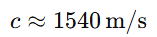
| Soft tissue (average) | 1540 |
| Muscle | ~1580 |
| Bone | ~3000–4000 |
Ultrasound systems assume a constant speed of 1540 m/s, which simplifies image reconstruction but introduces artifacts when tissues differ significantly.
4. Ultrasound Propagation in Tissue
When ultrasound waves enter the body, several phenomena occur simultaneously:
- Reflection
- Transmission
- Refraction
- Attenuation
- Scattering
Each one contributes to image formation—or degradation.

5. Acoustic Impedance: The Core Concept
5.1 Definition
Acoustic impedance Z is defined as:

Where:
- ρ = tissue density
- c = speed of sound
5.2 Why Acoustic Impedance Matters
Whenever an ultrasound wave encounters a boundary between two tissues with different impedances, part of the wave is reflected and part is transmitted.
This is the physical basis of ultrasound imaging.
5.3 Reflection at Tissue Interfaces
Reflection coefficient R:
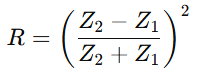
- Small impedance difference → weak echo
- Large impedance difference → strong echo
Examples:
- Soft tissue ↔ soft tissue → moderate reflection
- Soft tissue ↔ bone → very strong reflection
- Soft tissue ↔ air → almost total reflection
This explains why air is the enemy of ultrasound, and why gel is essential.
6. Attenuation: Why Ultrasound Weakens in Tissue
6.1 What Is Attenuation?
Attenuation is the loss of ultrasound intensity as it travels through tissue due to:
- Absorption (conversion to heat)
- Scattering
- Reflection losses
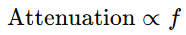
Attenuation increases with:
- Distance
- Frequency
6.2 Clinical Consequences
- High-frequency probes produce sharp images but shallow penetration
- Low-frequency probes penetrate deeply but with reduced resolution
Device design implication:
Transducer frequency selection depends entirely on the clinical application.
7. Scattering: Seeing Small Structures
7.1 What Causes Scattering?
Scattering occurs when ultrasound waves interact with:
- Red blood cells
- Small tissue inhomogeneities
- Microstructures smaller than the wavelength
Unlike specular reflection, scattering sends echoes in many directions.
7.2 Why Scattering Is Useful
- Enables visualization of soft tissue texture
- Essential for Doppler ultrasound (blood flow imaging)
Without scattering, Doppler imaging would not exist.
8. From Physics to the Ultrasound Transducer
8.1 The Piezoelectric Effect
Ultrasound transducers rely on piezoelectric materials (e.g., PZT):
- Electrical signal → mechanical vibration (wave emission)
- Returning echo → electrical signal (wave detection)
This dual role makes the transducer both a speaker and microphone.
8.2 Matching Layers and Coupling Gel
To reduce impedance mismatch:
- Matching layers gradually transition impedance
- Gel eliminates air gaps
These are engineering solutions to physical problems, not accessories.
9. Time-of-Flight and Image Formation
Ultrasound systems calculate depth using:
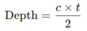
- t= echo return time
- Factor of 2 accounts for round trip
Every pixel in a B-mode image is essentially a time measurement converted into spatial information.
10. Common Artifacts Explained by Physics
| Artifact | Physical Cause |
|---|---|
| Acoustic shadow | Strong attenuation (bone, stones) |
| Enhancement | Low attenuation (fluid) |
| Reverberation | Multiple reflections |
| Refraction | Speed mismatch |
Engineers must understand artifacts to design better systems and interpret images correctly.
11. Biomedical Engineering Perspective
Understanding acoustic wave–tissue interaction is critical for:
- Designing transducers
- Optimizing frequency selection
- Improving image resolution
- Reducing artifacts
- Developing advanced modalities (Doppler, elastography, contrast imaging)
This physics directly informs:
- Hardware design
- Signal processing algorithms
- Clinical usability
12. Summary: The Big Picture
Ultrasound imaging systems are physics-driven biomedical devices.
- Acoustic waves propagate through tissue
- Tissue properties shape wave behavior
- Reflections create echoes
- Echoes become images
Every ultrasound image is a map of tissue acoustic properties, translated into grayscale by engineering systems built on solid physical principles.
References
- Kremkau, F. W. Diagnostic Ultrasound: Principles and Instruments. Elsevier.
- Szabo, T. L. Diagnostic Ultrasound Imaging: Inside Out. Academic Press.
- Bushberg, J. T., et al. The Essential Physics of Medical Imaging. Lippincott Williams & Wilkins.
- Hoskins, P. R., Martin, K., Thrush, A. Diagnostic Ultrasound: Physics and Equipment. CRC Press.
- Cobbold, R. S. C. Foundations of Biomedical Ultrasound. Oxford University Press.