
What Is Digital Radiography? Principles, Uses, and System Design
Digital Radiography (DR) systems represent a transformative advancement in medical imaging, replacing conventional film-based and computed radiography (CR) techniques with real-time, high-resolution digital image acquisition using flat-panel detector (FPD) technology. For biomedical engineers, understanding the underlying physics, system architecture, and regulatory landscape of DR is essential for procurement, maintenance, quality assurance, and innovation in clinical settings. DR systems are now the standard of care across hospitals, emergency departments, and outpatient imaging centers worldwide, offering superior image quality, reduced radiation dose, and seamless integration with digital health infrastructure. This article provides a thorough technical overview of DR systems — from core physics and detector design to clinical applications, safety standards, and emerging innovations — tailored specifically for the biomedical engineering professional.
1. What is a Digital Radiography (DR) System?
A Digital Radiography (DR) system is a modern medical imaging technology that uses flat-panel detectors (FPDs) to capture X-ray images in a fully digital format — eliminating the need for photographic film or phosphor storage plates. DR systems acquire, process, and display diagnostic-quality radiographic images within seconds, making them indispensable in contemporary clinical radiology. As part of the broader family of radiological devices, DR occupies a central role in diagnostic imaging workflows.
A Brief History: From Röntgen to Flat-Panel Detectors
The journey of radiographic imaging began on November 8, 1895, when Wilhelm Conrad Röntgen discovered X-rays at the University of Würzburg. Within weeks, the first radiographic image — of his wife’s hand — demonstrated the extraordinary clinical potential of this invisible radiation. For nearly a century, X-ray images were captured on silver-halide photographic film, a process that, while effective, required chemical development, physical storage, and introduced delays into clinical workflows. The 1980s brought a significant advancement with the introduction of Computed Radiography (CR), which used photostimulable phosphor (PSP) cassettes to store a latent image that was later read by a laser scanner. While CR digitized the image output, it still relied on a cassette-handling process and was considerably slower than what was to follow. The 1990s heralded the true digital era with the development of flat-panel detector (FPD) technology, enabling direct electronic readout of X-ray images without any intermediate step. By the early 2000s, DR had begun displacing CR in high-volume clinical environments, and today it is the dominant technology in new installations worldwide.
DR vs. Computed Radiography vs. Analog Film
It is important for biomedical engineers to distinguish clearly between these three generations of radiographic technology. Analog film requires wet chemical processing, produces a single physical copy, and offers no post-acquisition image manipulation. CR digitizes the process but still requires a cassette to be physically transported to a reader unit, introducing workflow latency and mechanical wear components. DR, by contrast, uses an FPD that is hardwired or wirelessly connected to the acquisition system, delivering images to the radiologist’s workstation — and to the PACS — in under 10 seconds. DR also offers superior detective quantum efficiency (DQE), which translates to better image quality at lower radiation doses. The pixel depth of DR images (typically 12–16 bits) supports an enormous dynamic range, enabling post-processing adjustments such as windowing, edge enhancement, and noise reduction that are simply impossible with analog film.
2. Why is Digital Radiography (DR) Used?
DR systems have become the preferred radiographic modality in modern healthcare for a convergence of clinical, operational, and regulatory reasons. Understanding these drivers is critical for biomedical engineers involved in capital equipment planning, clinical integration, and technology assessment.
Clinical Necessity and Diagnostic Value
Radiography remains the most frequently performed diagnostic imaging examination globally, with applications spanning chest imaging, musculoskeletal assessment, abdominal evaluation, trauma, and critical care monitoring. DR’s ability to deliver high-resolution images almost instantaneously is especially valuable in emergency and intensive care settings, where rapid diagnosis directly influences patient outcomes. The wide dynamic range of FPDs also reduces the frequency of retakes caused by overexposure or underexposure — a persistent issue with film-based systems. When compared to modalities such as CT scanners or SPECT scanners, DR delivers a rapid, cost-effective, and lower-dose first-line assessment for a vast range of clinical indications.
Dose Reduction and Patient Safety
One of the most compelling reasons for DR adoption is its ability to produce diagnostic-quality images at significantly reduced radiation doses compared to film and CR. The high DQE of modern FPDs — often exceeding 60–70% at zero frequency — means that fewer X-ray photons are wasted, and more of the incident radiation contributes usefully to image formation. This dose efficiency is particularly important in pediatric imaging, repeat examinations, and fluoroscopically guided procedures where cumulative dose is a concern. DR systems also support dose optimization tools such as automated exposure control (AEC) and dose area product (DAP) monitoring.
Operational and Economic Advantages
From an operational perspective, DR eliminates the recurring costs associated with film, chemicals, and cassette maintenance. Images are instantly available for remote review, teleradiology, and integration into electronic health records (EHRs). Workflow efficiency improves markedly — a busy radiology department can perform and transmit dozens of examinations per hour with DR, compared to the significantly slower throughput of CR or film. These factors make DR a sound long-term investment for healthcare systems of all sizes.
3. How Does a Digital Radiography (DR) System Work?
Understanding the functional physics and signal chain of a DR system is fundamental for biomedical engineers responsible for acceptance testing, quality control, and troubleshooting. The process from X-ray generation to displayed image involves several distinct and precisely engineered steps.
X-Ray Generation and Tissue Attenuation
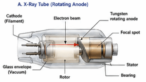
X-rays are generated in the X-ray tube by accelerating electrons (produced by thermionic emission from a heated tungsten filament cathode) across a high-voltage potential — typically 40–150 kVp for general radiography — toward a rotating tungsten anode target. The resulting bremsstrahlung and characteristic radiation spectrum exits through a collimated beam and passes through the patient. Different tissues attenuate the beam to varying degrees: dense cortical bone absorbs significantly more radiation than soft tissue or air-filled lungs, creating differential transmission patterns that encode anatomical information. This transmitted radiation then strikes the surface of the flat-panel detector, where it is converted into a digital image signal.
Direct and Indirect Flat-Panel Detector Conversion
The FPD is the technological heart of a DR system, and its conversion mechanism defines the detector type. In direct conversion detectors, the photoconductor material — most commonly amorphous selenium (a-Se) — absorbs incoming X-ray photons and directly generates electron-hole pairs that migrate under an applied electric field to charge-collection electrodes. This process skips an intermediate light conversion step, preserving spatial resolution. In indirect conversion detectors, a scintillator layer — typically cesium iodide (CsI) grown in a structured columnar crystal form, or gadolinium oxysulfide (GOS) as a powder coating — first converts X-ray photons into visible light photons. These light photons are then captured by an array of amorphous silicon (a-Si) photodiodes, which generate charge proportional to the light intensity. While indirect detectors introduce a slight lateral light spread that can reduce resolution, CsI’s columnar structure acts as a light guide, largely mitigating this effect. Similar principles of acoustic wave interaction govern signal generation in ultrasound imaging systems, though the physical mechanisms are entirely distinct.

TFT Readout, Digitization, and DICOM Processing
Beneath the conversion layer lies a matrix of thin-film transistors (TFTs), each associated with a pixel element and acting as a switch to read out accumulated charge. During image readout, gate lines are activated row by row, allowing stored charge from each pixel to flow through data lines to charge-sensitive amplifiers. The analog signal is then digitized by analog-to-digital converters (ADCs) to produce pixel values with a bit depth of 12 to 16 bits, corresponding to 4,096 to 65,536 gray levels. This high bit depth is what enables the exceptional dynamic range and post-processing flexibility of DR images. The raw digital data undergoes flat-field correction (to compensate for non-uniform detector response and defective pixels), gain calibration, and image processing algorithms including edge enhancement and noise reduction before being packaged into the DICOM (Digital Imaging and Communications in Medicine) format and transmitted to the PACS server for storage, distribution, and reporting.
4. What Are the Main Components of a DR System?
A complete DR system is an integrated assembly of several interdependent subsystems. For biomedical engineers, a thorough understanding of each component is necessary for system commissioning, preventive maintenance, and fault diagnosis.
X-Ray Tube and High-Voltage Generator
The X-ray tube is a vacuum diode containing a cathode (filament) and a rotating tungsten anode. The cathode emits electrons by thermionic emission, which are accelerated by the high-voltage potential applied by the high-voltage generator (typically a high-frequency inverter type operating at 40–150 kVp). The rotating anode distributes the heat load across a larger focal track, enabling the high tube currents (mA) needed for short exposure times. Tube parameters — kVp, mA, and exposure time (ms) — directly determine the quantity and quality of the X-ray beam and are critical to image quality and patient dose management. The focal spot size (typically 0.6–1.2 mm for general DR) influences geometric sharpness and is a key specification for biomedical engineers during acceptance testing.
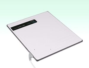
Flat-Panel Detector (FPD)
The FPD is the primary image receptor and the most technically sophisticated component of the DR system. Modern FPDs are available in various sizes (e.g., 35×43 cm for general radiography) and pixel pitches (typically 100–200 µm). Key performance metrics include DQE (detective quantum efficiency), MTF (modulation transfer function — typically >50% at 2–3 lp/mm for CsI detectors), noise power spectrum (NPS), and dynamic range. FPDs must be periodically calibrated for dark-field offset, gain uniformity, and defective pixel correction. Wireless FPDs, increasingly common in portable and trauma applications, incorporate internal batteries and Wi-Fi or Bluetooth communication modules, introducing additional considerations for electromagnetic compatibility (EMC) and cybersecurity.
Automatic Exposure Control (AEC)
The Automatic Exposure Control (AEC) system terminates the X-ray exposure when a predetermined amount of radiation has reached the detector, ensuring consistent image quality regardless of patient body habitus. AEC ionization chambers are positioned in front of or behind the detector, and their signals are processed to terminate the exposure at the correct dose. From a regulatory perspective, AEC performance is subject to quality assurance testing requirements under standards such as IEC 62494 and national regulatory frameworks.
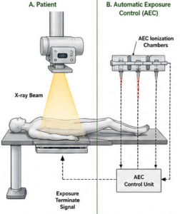
Image Processing Workstation and PACS/DICOM Integration
The image processing workstation receives raw detector data, applies flat-field and gain corrections, executes proprietary image enhancement algorithms, and formats the image as a DICOM object. The workstation communicates with the PACS (Picture Archiving and Communication System) via DICOM protocols — including DICOM Store, Worklist, and Print services — enabling seamless integration with radiology information systems (RIS) and hospital information systems (HIS). Biomedical engineers must ensure correct DICOM conformance, appropriate data security measures, and regular software validation as part of ongoing system management. The regulatory classification of DR systems, including FDA 510(k) requirements, is discussed in detail in our article on how biomedical devices are classified.

5. What Types and Variants of DR Systems Exist?
DR systems are not monolithic — they encompass several distinct detector technologies and system configurations, each with specific performance characteristics, clinical applications, and cost profiles. A thorough understanding of these variants equips biomedical engineers to make informed recommendations during capital equipment procurement and technology assessment.
Detector Technology Variants: Direct vs. Indirect Conversion
As described in Section 3, the fundamental distinction among DR detectors lies in their conversion mechanism. Direct conversion detectors (using a-Se) offer the highest intrinsic spatial resolution because there is no light-spreading step, making them particularly valuable in mammography and high-resolution chest imaging. Indirect conversion detectors using CsI offer an excellent balance of DQE, sensitivity, and resolution, and dominate the general radiography market due to their robustness and cost-effectiveness. Indirect conversion detectors using GOS (gadolinium oxysulfide) are lower in cost but exhibit somewhat lower DQE and resolution compared to CsI, and are often found in portable or budget-constrained installations. Manufacturers such as Carestream, Canon, Fujifilm, Agfa, Varex, GE, Siemens, and Philips offer products across these categories, each with proprietary signal processing optimizations.
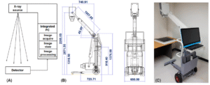
System Configuration Variants
Beyond detector technology, DR systems vary in their physical configuration. Fixed room DR systems are ceiling- or floor-mounted installations with dedicated generators and positioning systems, offering the highest image quality and throughput. Retrofit DR systems replace existing film or CR cassette holders with FPD units, leveraging existing X-ray tube and generator infrastructure to reduce upgrade costs. Portable/mobile DR systems incorporate battery-powered generators and wireless FPDs mounted on mobile stands, enabling bedside imaging in ICUs, emergency departments, and operating theaters. Wireless DR panels are standalone FPD cassettes that can be used with virtually any existing X-ray generator, offering maximum flexibility for multi-room environments.
Comparison of DR Technology Types
The following table provides a structured comparison of the major DR and legacy radiography technologies, highlighting their key differentiating characteristics for biomedical engineering evaluation:
| Type | Detection Method | Image Quality | Dose Efficiency | Typical Use Case |
|---|---|---|---|---|
| Direct DR (a-Se) | X-ray → charge (amorphous selenium photoconductor) | Highest spatial resolution; excellent MTF; minimal blur | High DQE (>65%); efficient at low doses | Mammography, high-resolution chest, extremities |
| Indirect DR (CsI) | X-ray → light (CsI scintillator) → charge (a-Si photodiodes) | Very good; MTF >50% at 2–3 lp/mm; slight light spread mitigated by columnar CsI | High DQE (>60–70%); excellent sensitivity | General radiography, chest, MSK, trauma, ICU |
| Indirect DR (GOS) | X-ray → light (gadolinium oxysulfide powder screen) → charge (a-Si photodiodes) | Good; lower MTF than CsI due to greater light spread | Moderate DQE (~50–60%); adequate for most applications | Portable systems, budget installations, follow-up imaging |
| Computed Radiography (CR) | X-ray → latent image on photostimulable phosphor (PSP) cassette → laser readout | Moderate; limited by phosphor light spread and cassette reader optics | Lower DQE (~30–40%); higher patient dose required vs. DR | Legacy systems; low-volume or resource-limited settings |
For biomedical engineers, this comparative framework is essential when evaluating new system acquisitions or planning technology upgrades. The choice between detector types must balance image quality requirements, patient population, throughput demands, and total cost of ownership — all within the compliance requirements of standards such as IEC 60601-1, IEC 62494, and applicable FDA 510(k) clearance pathways.
6. What Are the Main Benefits of a DR System?
Digital Radiography systems represent one of the most significant leaps forward in diagnostic imaging technology. For biomedical engineers tasked with evaluating, deploying, or maintaining these systems, understanding their core benefits is essential to justifying investment and optimizing clinical performance. These advantages span workflow efficiency, patient safety, image quality, and institutional sustainability.
6.1 Accelerated Clinical Workflow and Operational Efficiency
One of the most immediately measurable advantages of DR is speed. Images are typically available at the acquisition workstation in under 10 seconds, compared to several minutes required for computed radiography (CR) or film-based systems. This dramatically reduces patient throughput time in high-volume departments such as emergency radiology, orthopedics, and chest imaging. Integration with Picture Archiving and Communication Systems (PACS) via DICOM 3.0 allows instant image routing to radiologist workstations, remote reading stations, and electronic health records (EHR) — eliminating the physical transport of films or cassettes. Retake rates are also significantly reduced because real-time image preview allows technologists to immediately verify positioning and exposure adequacy, further streamlining the clinical process. Learn more about the broader landscape of imaging technology in our overview of Radiological Devices.
6.2 Radiation Dose Reduction and Patient Safety
DR systems offer a 30–70% reduction in radiation dose compared to conventional film-screen systems, depending on the clinical application, anatomical region, and detector technology employed. This reduction is achieved through the high detective quantum efficiency (DQE) of flat-panel detectors, which convert a greater proportion of incident X-ray photons into diagnostic signal. The ALARA (As Low As Reasonably Achievable) principle is more practically enforced with DR because exposure index (EI) monitoring — standardized under IEC 62494-1 — provides immediate feedback on whether the patient received an appropriate dose. Automatic exposure controls (AEC) further optimize technique factors in real time.
6.3 Superior Image Quality and Environmental Sustainability
Post-processing capabilities in DR — including windowing, edge enhancement, noise reduction algorithms, and bone suppression filters — allow radiologists to extract diagnostic information that would be impossible to recover from a fixed-exposure analog film. The wide dynamic range exceeding 10,000:1 ensures that both high-density (bone) and low-density (soft tissue) structures are simultaneously visualized. From an environmental and operational standpoint, DR eliminates the need for chemical developers, fixers, and film disposal processes — reducing hazardous waste, chemical storage requirements, and associated regulatory compliance costs, making DR a more sustainable long-term choice for healthcare facilities.
7. What Are the General Risks and Limitations of DR Systems?
While DR systems deliver substantial clinical and operational benefits, biomedical engineers must also critically assess the risks, constraints, and failure modes inherent to this technology. A balanced risk-benefit analysis is fundamental to responsible procurement, commissioning, and ongoing quality assurance of DR installations.
7.1 Radiation Exposure and the ALARA Challenge
Despite dose efficiency improvements, DR systems do not eliminate ionizing radiation risk. A well-documented concern is dose creep — the tendency for technologists to increase exposure techniques above optimal levels because the DR detector’s wide dynamic range masks overexposure through automatic image normalization. Without active EI monitoring and dose audit programs, patients can receive significantly higher doses than clinically necessary. Biomedical engineers must ensure that exposure index target values (EIT) are configured correctly per the IEC 62494-1 standard, and that regular dose audits are integrated into the facility’s quality assurance framework. Radiation protection measures, shielding adequacy, and collimation practices must be routinely evaluated. Ethical responsibilities around patient dose are explored further in our article on Ethical Considerations in Biomedical Engineering.
7.2 High Capital Cost, Detector Degradation, and Artifacts
DR systems carry a significant initial capital investment ranging from $50,000 to over $200,000, depending on detector type, generator integration, and whether fixed or portable configurations are required. Flat-panel detectors (FPDs) are particularly susceptible to degradation over time — dead pixels accumulate, scintillator layers can delaminate, and amorphous silicon TFT arrays lose sensitivity. Artifacts such as grid cutoff lines, ghost images (lag artifacts), fixed-pattern noise, and edge enhancement distortion can compromise diagnostic quality if preventive maintenance and calibration schedules are not rigorously maintained. Motion blur, especially in pediatric or uncooperative patients, remains a limitation tied to detector readout speed and exposure timing.
7.3 Cybersecurity, DICOM Vulnerabilities, and Data Privacy
As DR systems become deeply integrated into hospital network infrastructure, cybersecurity risks have grown substantially. DICOM 3.0 — while the universal standard for medical image communication — was not originally designed with robust security in mind. Unencrypted DICOM data transmissions, weak authentication on PACS servers, and unpatched operating systems in imaging workstations create exploitable vulnerabilities. Patient data breaches, ransomware attacks on radiology networks, and unauthorized image access are documented real-world threats. Biomedical engineers must advocate for TLS encryption of DICOM traffic, role-based access controls, regular penetration testing, and compliance with HIPAA (in the US) or GDPR (in the EU) frameworks to protect patient data integrity.
8. How is Digital Radiography Evolving? Recent Innovations
The DR landscape is advancing rapidly, driven by breakthroughs in detector physics, artificial intelligence, and system miniaturization. Biomedical engineers working in clinical engineering, R&D, or procurement must stay current with these developments, as they redefine what performance metrics, clinical capabilities, and maintenance profiles to expect from next-generation systems. These innovations are also reshaping the skill sets required — as outlined in our guide on Top Skills Every Biomedical Engineer Should Master.
8.1 Artificial Intelligence Integration in DR Imaging
AI is transforming DR at multiple points in the imaging chain. Deep learning-based noise reduction algorithms (such as those embedded in Fujifilm’s ISE — Irradiation Side Sampling — and Carestream’s AI-Powered Noise Reduction) significantly improve image quality at reduced doses by distinguishing true anatomical signal from quantum noise. Bone suppression software digitally removes rib and clavicle overlays in chest radiographs, improving sensitivity for pulmonary nodule detection. AI-driven auto-triage and critical finding detection systems — such as Aidoc, Qure.ai, and Nanox.AI — flag potential pneumothorax, consolidation, cardiomegaly, or fractures in the PACS worklist before radiologist review, reducing time-to-diagnosis in emergency settings. Automated collimation detection, patient positioning assistance, and exposure optimization are also increasingly AI-driven features in premium DR installations.
8.2 Wireless and Portable DR Advances
Wireless flat-panel detectors have revolutionized bedside and emergency imaging. Products such as the Carestream DRX-1 and DRX-2530C, Canon CXDI-710C wireless detector, and Fujifilm FDR D-EVO II offer battery-powered operation, lightweight carbon fiber housings, and Wi-Fi or proprietary RF connectivity. These detectors can be retrofitted into existing bucky systems or used in conjunction with portable X-ray generators for ICU, ER, and OR applications. Siemens Healthineers’ MOBILETT Mira Max and GE Healthcare’s Optima XR646 represent complete portable DR systems optimized for critical care environments, featuring automated DR workflow and dose management integration. Detector drop resistance, battery life (typically 200–400 exposures per charge), and wireless latency are key engineering parameters to evaluate.
8.3 Photon-Counting Detectors, Dual-Energy Subtraction, and Spectral DR
Emerging photon-counting detector (PCD) technology — already transforming CT imaging (see our CT Scanner overview) — is now being explored for projection radiography, offering near-zero electronic noise, intrinsic energy discrimination, and superior DQE at low dose levels. Dual-energy subtraction DR, available on systems such as the Philips DigitalDiagnost C90 and GE Precision DR, acquires two exposures at different kVp settings to generate soft tissue-only and bone-only images, enhancing detection of pulmonary nodules and calcified lesions. Spectral DR and tomosynthesis integration are extending the diagnostic utility of planar radiography toward quasi-3D volumetric capabilities, blurring the boundary between conventional radiography and advanced cross-sectional imaging.
9. Key Takeaways and Tips for Biomedical Engineers
Digital Radiography systems sit at the intersection of radiation physics, electronics engineering, clinical workflow design, and regulatory compliance. For biomedical engineers, mastering DR technology requires both technical depth and practical operational knowledge. The following guidance consolidates critical considerations for anyone involved in the procurement, commissioning, maintenance, or quality assurance of DR systems.
9.1 Critical Performance Metrics Every Engineer Must Understand
When evaluating or testing DR systems, prioritize the following engineering parameters:
- Detective Quantum Efficiency (DQE): The gold-standard metric for detector efficiency. A DQE(0) above 65–75% at relevant spatial frequencies indicates a high-quality detector. DQE is frequency-dependent and must be assessed across the full MTF range.
- Modulation Transfer Function (MTF): Characterizes spatial resolution. Clinical DR detectors typically achieve 2–5 line pairs per millimeter (lp/mm). Higher MTF values indicate sharper image reproduction of fine anatomical detail.
- Noise Power Spectrum (NPS): Quantifies noise texture and magnitude as a function of spatial frequency. Together with MTF, NPS defines the system’s overall noise-resolution trade-off.
- Exposure Index (EI) and Deviation Index (DI): Standardized per IEC 62494-1 and implemented across all major manufacturers under DICOM tag (0018,1405). A DI of 0 indicates optimal exposure; values beyond ±1 warrant investigation.
- Dynamic Range: Should exceed 10,000:1 for adequate latitude in high-contrast anatomical regions.
9.2 Procurement, Regulatory Compliance, and Maintenance Best Practices
During procurement, verify that equipment carries relevant regulatory clearances: FDA 510(k) clearance for the US market, CE marking under MDR 2017/745 for Europe, and ISO 13485 quality management certification from the manufacturer. Compliance with IEC 60601-1 (electrical safety) and NEMA XR-29 (Smart Dose — dose management features in radiographic equipment) should be contractually confirmed. Review the device classification framework detailed in our article on How Biomedical Devices Are Classified. Establish a preventive maintenance schedule that includes detector calibration (gain/offset/defect maps), generator kVp and mAs accuracy verification, AEC consistency testing, and image quality phantom assessments using CDRAD or Leeds test objects. Document all maintenance activities in a validated CMMS (Computerized Maintenance Management System) to support regulatory audits.
9.3 Career Relevance and Continuous Professional Development
Proficiency in DR systems is highly valuable across clinical engineering, medical imaging physics, health technology assessment, and regulatory affairs roles. Biomedical engineers should seek hands-on training with major platform ecosystems (Carestream, Canon, Fujifilm, Agfa), pursue certifications such as the CBET (Certified Biomedical Equipment Technician) or CRES (Certified Radiology Equipment Specialist), and engage with professional bodies including AAPM, IPEM, and ACCE. Staying current with AI integration trends, cybersecurity requirements, and evolving IEC/DICOM standards will remain critical as DR technology continues its rapid evolution.
References
- International Atomic Energy Agency (IAEA). Digital Radiography: A Practical Approach. IAEA Human Health Series No. 28. Vienna: IAEA; 2014. Available at: https://www.iaea.org/publications/10552/digital-radiography
- International Electrotechnical Commission. IEC 62494-1:2008 — Medical Electrical Equipment: Exposure Index of Digital X-Ray Imaging Systems — Part 1: Definitions and Requirements for General Radiography. Geneva: IEC; 2008. Available at: https://www.iec.ch/standard/47007
- National Electrical Manufacturers Association (NEMA). XR 29-2013: Standard Attributes on CT Equipment Related to Dose Optimization and Management. Rosslyn, VA: NEMA; 2013. Available at: https://www.nema.org/standards/pages/xr-29
- National Electrical Manufacturers Association (NEMA). Digital Imaging and Communications in Medicine (DICOM) Standard — PS3 Series. Rosslyn, VA: NEMA; 2023. Available at: https://www.dicomstandard.org/
- Samei E, Ranger NT, Dobbins JT III, Chen Y. Intercomparison of methods for image quality characterization. I. Modulation transfer function. Medical Physics. 2006;33(5):1454–1465. doi: 10.1118/1.2188816
- Seibert JA, Boone JM. X-ray imaging physics for nuclear medicine technologists. Part 2: X-ray interactions and image formation. Journal of Nuclear Medicine Technology. 2005;33(1):3–18. Available at: https://tech.snmjournals.org/content/33/1/3
- US Food and Drug Administration. Guidance for Industry and FDA Staff: Radiological Devices — Premarket Notification [510(k)] Submissions. Silver Spring, MD: FDA; 2019. Available at: https://www.fda.gov/medical-devices/premarket-submissions/510k
- Carestream Health. DRX Detector Technology — Technical White Paper: Advancing Clinical Workflow with Wireless Flat-Panel Detectors. Rochester, NY: Carestream Health; 2022. Available at: https://www.carestream.com/resources/white-papers
- Canon Medical Systems. CXDI Series Wireless Digital Radiography — Technical Specifications and Clinical Applications. Otawara, Japan: Canon Medical Systems; 2023. Available at: https://global.medical.canon/products/radiography/wireless-dr
- Fujifilm Medical Systems. FDR D-EVO II Flat Panel Detector — Engineering and Clinical Performance Documentation. Tokyo: Fujifilm Holdings; 2022. Available at: https://www.fujifilm.com/healthcare/radiography/detectors
