
Cone Beam CT (CBCT) for Biomedical Engineers: Principles, Components, Clinical Applications, and Emerging Innovations
Cone Beam Computed Tomography (CBCT) represents one of the most significant advances in volumetric medical imaging of the past three decades, offering biomedical engineers and clinicians a compact, high-resolution, lower-dose alternative to conventional CT scanning for targeted anatomical regions. By exploiting a divergent, cone-shaped X-ray beam in combination with a flat-panel detector and sophisticated reconstruction algorithms, CBCT systems can generate isotropic 3D volumetric datasets with voxel resolutions as fine as 0.1 mm in a single gantry rotation, making them indispensable in dentistry, ENT, orthopedics, and interventional radiology. This article provides a thorough technical and clinical exploration of CBCT for biomedical engineering professionals, covering its underlying physics, system architecture, clinical variants, benefits, limitations, and the emerging innovations reshaping the field.

Table of Contents
- What is a Cone Beam CT?
- Why is Cone Beam CT used?
- How does Cone Beam CT work?
- What are the main components of a Cone Beam CT?
- What types and variants of Cone Beam CT exist?
- What are the main benefits of Cone Beam CT?
- What are the general risks and limitations of Cone Beam CT?
- How is Cone Beam CT evolving? Recent innovations
- Key takeaways and tips for biomedical engineers
What is a Cone Beam CT?
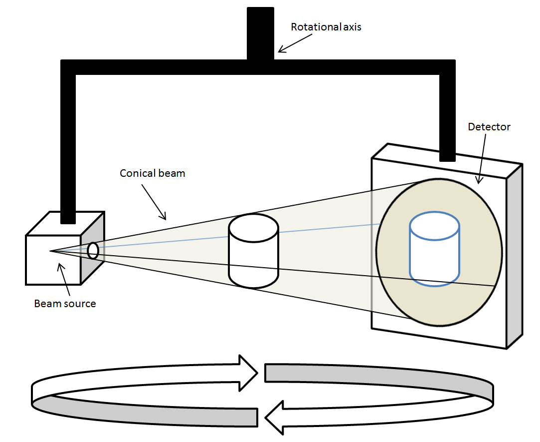
Cone Beam Computed Tomography (CBCT) is a specialized medical imaging modality that uses a divergent, cone-shaped X-ray beam to acquire a full volumetric dataset of a targeted anatomical region in a single rotational pass around the patient. Unlike conventional CT scanners, which employ a fan-beam geometry requiring multiple helical passes to cover a volume, CBCT irradiates the entire region of interest simultaneously, significantly reducing scan time and radiation exposure while delivering comparable spatial resolution for hard-tissue structures.
Definition and Core Concept
At its core, CBCT captures hundreds of two-dimensional projection images from multiple angles as the X-ray source and detector rotate around the patient. These projections are then processed using modified cone-beam reconstruction algorithms—most notably the Feldkamp-Davis-Kress (FDK) algorithm—to generate a three-dimensional isotropic volumetric dataset. The resulting image can be reformatted in any plane—axial, coronal, or sagittal—at true 1:1 scale, enabling precise anatomical measurements critical for surgical planning and device placement.
Historical Development
CBCT technology evolved from conventional computed tomography research during the 1980s, initially finding application in angiography and vascular imaging. The pivotal shift toward clinical utility came in the 1990s and early 2000s when advances in low-power X-ray tube technology and the commercialization of amorphous silicon flat-panel detectors (FPDs) enabled the development of compact, clinic-suitable units. The dental and maxillofacial fields were among the earliest adopters, rapidly establishing CBCT as the standard of care for implant planning, orthodontic analysis, and temporomandibular joint evaluation. Today, CBCT platforms from manufacturers such as Planmeca, Dentsply Sirona, KaVo, iCAT (Envista), Vatech, and NewTom serve a broad spectrum of clinical specialties. The technology also intersects closely with radiological device frameworks that govern diagnostic imaging systems across healthcare settings.
Distinction from Conventional CT
While both modalities rely on X-ray attenuation principles, CBCT differs fundamentally from conventional CT in beam geometry, detector type, X-ray tube power, and reconstruction methodology. Conventional CT uses high-output rotating-anode tubes and fan-beam geometry optimized for soft-tissue contrast across large body volumes. CBCT uses low-power fluoroscopy-grade tubes, area flat-panel detectors, and cone-beam geometry optimized for high-resolution hard-tissue imaging within a limited field of view (FOV). This distinction makes CBCT highly effective for dental, skeletal, and interventional applications, while conventional CT remains superior for thoracic, abdominal, and soft-tissue oncological imaging.
Why is Cone Beam CT used?
CBCT has been widely adopted across multiple clinical disciplines because it addresses a specific and clinically compelling combination of needs: high spatial resolution for hard-tissue and bony structures, reduced patient radiation exposure compared to conventional CT, compact system footprint suitable for outpatient and clinic environments, and true three-dimensional visualization that two-dimensional radiography fundamentally cannot provide. Understanding why CBCT is used requires appreciating both the clinical unmet needs it addresses and the engineering trade-offs it makes relative to other imaging modalities.
Clinical Indications Driving Adoption
In dentistry and oral surgery, CBCT is the gold standard for dental implant planning, assessment of impacted teeth, evaluation of the temporomandibular joint (TMJ), orthodontic cephalometric analysis, and identification of root canal morphology. In ENT and maxillofacial surgery, it supports the evaluation of jaw tumors, sinonasal anatomy, nerve canal positioning, and craniofacial anomalies. Orthopedic applications leverage CBCT for detailed extremity and joint imaging where portable, weight-bearing, or upright scanning configurations provide functional biomechanical data unavailable from supine conventional CT. In interventional radiology, CBCT integrated with C-arm fluoroscopy systems provides real-time 3D guidance for biopsies—with reported accuracy rates approaching 98%—as well as stent placement, embolization procedures, and abscess drainage, areas closely related to angiography systems used in vascular intervention.
Advantages Over Conventional 2D Radiography
Conventional periapical and panoramic radiography remain cost-effective for routine dental screening, but they inherently superimpose anatomical structures onto a flat image plane, introducing geometric distortion and obscuring critical three-dimensional relationships. CBCT eliminates this limitation entirely, providing true volumetric datasets at 1:1 scale. This is particularly important for pre-surgical assessment of bone density and volume, proximity of vital structures such as the inferior alveolar nerve to planned implant sites, and morphological evaluation of bony pathologies that would be ambiguous on two-dimensional projections.
Comparison with Other Imaging Modalities
When biomedical engineers evaluate imaging modality selection, CBCT occupies a well-defined niche. Compared to MRI scanners, CBCT delivers superior spatial resolution for calcified and bony structures without the contraindications associated with strong magnetic fields, though MRI vastly outperforms CBCT in soft-tissue contrast. Compared to ultrasound systems, CBCT provides unambiguous hard-tissue visualization that ultrasound cannot penetrate. Compared to nuclear medicine modalities such as PET scanners or SPECT scanners, CBCT does not require radiopharmaceutical administration and delivers structural rather than functional information. This modality specificity makes CBCT a critical component of a multimodal imaging strategy in modern clinical practice.
How does Cone Beam CT work?
The operational principles of CBCT are rooted in the physics of X-ray attenuation, area detector technology, and cone-beam reconstruction mathematics. Biomedical engineers working with CBCT systems must understand the complete imaging chain—from X-ray generation and beam collimation, through projection acquisition, to volumetric reconstruction—to optimize system performance, troubleshoot image quality issues, and ensure radiation safety compliance.
X-Ray Generation, Beam Geometry, and Projection Acquisition
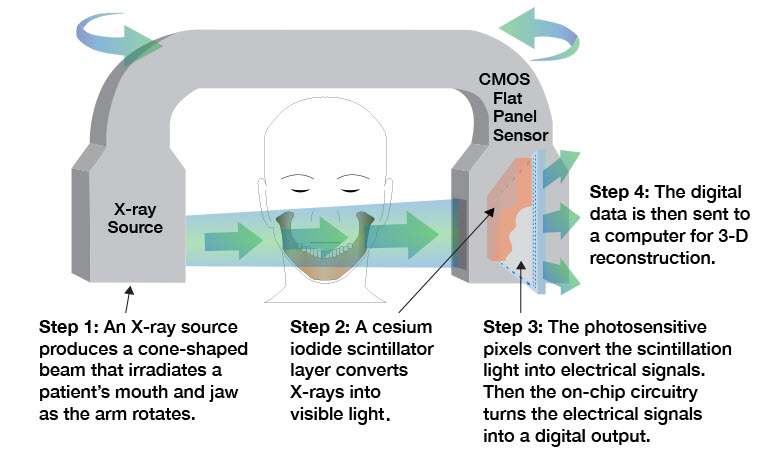
CBCT systems employ a low-power X-ray tube operating typically at 90–120 kVp and 1–15 mA—parameters markedly lower than the high-output rotating-anode tubes used in conventional CT, which often operate at 120–140 kVp and 100–400 mA. The X-ray beam is collimated into a divergent cone shape that illuminates the entire selected field of view (FOV) simultaneously, rather than the narrow fan beam used in helical CT. As the X-ray source and its opposing flat-panel detector rotate around the patient through an arc of 180° to 360°, a series of 150 to 1024 sequential two-dimensional projection images—also called raw frames or offset projections—are captured at incremental angular positions. Each projection encodes the cumulative X-ray attenuation along every ray path through the volume, following the Beer-Lambert law of exponential attenuation: I = I₀ · e^(−μx), where μ is the linear attenuation coefficient of the tissue and x is the path length. Tissues with higher density and atomic number (such as cortical bone and dental enamel) attenuate X-rays more strongly, appearing as bright regions on the reconstructed volume, while air-filled cavities appear dark. This is the same physical principle underlying fluoroscopy systems and conventional CT, though the geometric configuration and detector technology differ significantly.
Flat-Panel Detector and Signal Processing
The flat-panel detector (FPD)—typically composed of amorphous silicon (a-Si) with a cesium iodide (CsI) scintillator layer, or alternatively a charge-coupled device (CCD) array coupled to an image intensifier—converts transmitted X-ray photons into electrical signals that are digitized into projection images. The FPD’s area detection capability is the fundamental engineering feature that distinguishes CBCT from fan-beam CT: rather than measuring attenuation along a single slice at each gantry position, the FPD captures a two-dimensional projection of the entire cone-beam volume simultaneously. This enables volumetric data acquisition in a single rotation, but also introduces increased scatter radiation reaching the detector compared to the tightly collimated fan-beam geometry of conventional CT—a key contributor to the elevated image noise and reduced soft-tissue contrast that characterize CBCT images.
Image Reconstruction: The FDK Algorithm
Volumetric reconstruction from cone-beam projections is most commonly performed using the Feldkamp-Davis-Kress (FDK) algorithm, a filtered backprojection method adapted for cone-beam geometry. In the FDK approach, each acquired projection is first filtered using a ramp (Ram-Lak) filter in the frequency domain to correct for the blurring introduced by simple backprojection, then the filtered projections are backprojected along their original ray paths through the reconstruction volume. The FDK algorithm is computationally efficient and produces high-quality results for small cone angles and circular acquisition orbits, which corresponds well to the limited FOV and single-rotation acquisition geometry of most clinical CBCT systems. The reconstructed volume consists of isotropic voxels—cubic volume elements with equal dimensions in all three spatial directions—as small as 0.1 mm, enabling multiplanar reformatting (MPR) in axial, coronal, and sagittal planes at true 1:1 anatomical scale without loss of resolution in any orientation. This isotropic resolution is a critical advantage over conventional CT, which often exhibits anisotropic voxels with larger slice thickness in the z-axis.
What are the main components of a Cone Beam CT?
A CBCT system is an integrated electromechanical and digital imaging platform comprising several interdependent subsystems. Biomedical engineers responsible for procurement, installation, maintenance, and quality assurance of these systems must be familiar with the function, specifications, and failure modes of each major component. The principal hardware and software subsystems are described below.
X-Ray Source and High-Voltage Generator
The X-ray tube in a CBCT system is a low-power, stationary- or rotating-anode fluoroscopy-grade tube designed for continuous or pulsed exposure during the rotational acquisition. Operating at 90–120 kVp and 1–15 mA, these tubes generate a polychromatic X-ray spectrum that is collimated into the cone-beam geometry by a beam-shaping collimator assembly. The high-voltage generator supplies the precise, stable kilovoltage and milliamperage settings that determine beam energy and flux. Compared to the high-output rotating-anode tubes found in conventional CT scanners—which can operate at 400+ mA with duty cycles demanding liquid-cooled anodes—CBCT tubes are engineered for lower heat loading, contributing to the system’s compact form factor and lower cost. Beam filtration (typically aluminum or copper) is applied to harden the beam and reduce patient dose from low-energy photons that would otherwise be absorbed in superficial tissues without contributing diagnostic information.
Flat-Panel Detector and Image Intensifier Variants
The area detector is the defining component of any CBCT system and directly determines image quality parameters including spatial resolution, dynamic range, and noise performance. The dominant technology is the indirect-conversion amorphous silicon (a-Si) flat-panel detector, which uses a CsI scintillator layer to convert X-ray photons to visible light, which is then detected by a photodiode array and read out via thin-film transistor (TFT) circuitry. Some legacy and lower-cost systems employ CCD sensors coupled to image intensifiers, which offer acceptable performance but are more susceptible to geometric distortion and have a smaller active area. Modern FPDs used in high-end CBCT systems feature active areas of 20×20 cm to 30×30 cm, pixel pitches of 100–200 µm, and high frame rates (up to 30 fps) to support rapid acquisition protocols. The detector’s detective quantum efficiency (DQE) is a critical engineering metric governing how effectively it converts incident X-ray quanta into useful signal, directly impacting image quality at a given dose level. This technology is closely related to the detector systems used in mammography systems and digital fluoroscopy platforms.
Rotating Gantry and Image Reconstruction Software
The rotating gantry maintains precise geometric alignment between the X-ray source and detector throughout the acquisition arc (180°–360°), as any mechanical wobble or misalignment directly introduces geometric artifacts into the reconstructed volume. Dental CBCT units commonly employ a C-arm or rotating yoke configuration with the patient seated upright, minimizing footprint. Larger orthopedic and interventional CBCT systems may use ring gantry designs similar to conventional CT. The image reconstruction workstation executes the FDK filtered backprojection algorithm—often GPU-accelerated for real-time or near-real-time reconstruction—and provides multiplanar reformatting, volume rendering, and measurement tools. Leading software platforms integrate DICOM-compliant export, implant planning overlays, and AI-assisted segmentation modules. Regulatory compliance of the complete system, including the software, falls under FDA device classification frameworks and IEC 60601 safety standards.
What types and variants of Cone Beam CT exist?
CBCT technology has diversified considerably since its introduction, with purpose-built variants engineered for specific clinical applications and anatomical regions. Each variant reflects deliberate engineering trade-offs in field of view, X-ray tube power, detector size, patient positioning, and reconstruction protocols. Understanding these variants is essential for biomedical engineers involved in technology assessment, procurement, or clinical integration.
Clinical Variants by Application Domain
Dental and maxillofacial CBCT systems represent the largest installed base globally. These units are optimized for head and neck anatomy, offering small to medium FOVs (4×4 cm to 17×13 cm) at sub-millimeter voxel resolution for implant planning, orthodontics, endodontics, and TMJ evaluation. ENT-focused CBCT systems extend coverage to include the sinonasal complex, temporal bones, and cranial base, supporting sinus surgery planning and cochlear implant assessment. Orthopedic CBCT systems, increasingly offered in weight-bearing upright configurations, target extremities and large joints such as the knee, ankle, foot, wrist, and hip, providing functional biomechanical data under physiological loading conditions—a capability unavailable with conventional supine CT. Interventional CBCT, typically integrated into C-arm fluoroscopy platforms used in angiography suites, enables intra-procedural 3D guidance for vascular and non-vascular interventions including tumor ablation, stent deployment, and drainage procedures, complementing the capabilities described in dedicated angiography system platforms. Full-body CBCT variants with large FOVs are emerging for applications such as radiation therapy simulation and whole-spine scoliosis assessment.
Comparative Overview of CBCT Variants
The following table summarizes the key characteristics of the major CBCT system types across clinically and technically relevant parameters, enabling direct comparison for device evaluation and procurement decision-making.
| Type | FOV | Typical Use | Dose vs Conventional CT | Key Manufacturers |
|---|---|---|---|---|
| Dental CBCT | Small–Medium (4×4 cm to 17×13 cm) | Implant planning, orthodontics, endodontics, TMJ, impacted teeth | 6–15× lower | Planmeca, Dentsply Sirona, KaVo, iCAT (Envista), Vatech, NewTom |
| ENT CBCT | Medium (10×10 cm to 20×17 cm) | Sinus surgery, temporal bone, jaw tumors, nerve mapping, cochlear implants | 6–12× lower | Planmeca, Carestream, NewTom, Vatech |
| Orthopedic CBCT | Medium–Large (20×20 cm to 30×30 cm) | Extremity and joint imaging (knee, ankle, wrist, hip); weight-bearing studies | 5–10× lower | Carestream (OnSight), Planmeca, CurveBeam |
| Interventional CBCT | Large (25×25 cm to 40×30 cm) | Biopsy guidance, stent placement, embolization, abscess drainage, vascular interventions | Variable; comparable to or slightly lower than CT per procedure | Siemens Healthineers, Philips, GE Healthcare, Canon Medical |
| Full-Body CBCT | Large–Extra Large (≥40 cm axial coverage) | Radiation therapy simulation, whole-spine scoliosis assessment, large FOV oncology | Comparable to conventional CT in some protocols | Varian (OBI), Elekta, Carestream |
Engineering Considerations in Variant Selection
From an engineering perspective, the selection of a CBCT variant for a given clinical environment involves evaluation of several interdependent parameters: the required FOV determines detector size and tube power requirements; the target anatomical structures determine the acceptable voxel size and spatial resolution specifications; the patient population and scan frequency determine thermal loading requirements for the X-ray tube; and the clinical workflow determines whether upright, seated, or recumbent patient positioning is necessary. Integration with existing DICOM infrastructure, PACS systems, and surgical navigation platforms—particularly relevant for interventional and orthopedic variants—adds another layer of systems engineering complexity. Radiation dose implications differ substantially across variants, and all CBCT systems must be evaluated against the ALARA (As Low As Reasonably Achievable) principle as codified in ICRP Publication 103 and enforced through regulatory frameworks including FDA 510(k) premarket clearance and IEC 60601 electrical safety standards. Biomedical engineers involved in CBCT procurement should also cross-reference bone densitometry considerations with DEXA scanner capabilities when evaluating orthopedic imaging workflows, as the two modalities serve complementary but distinct diagnostic roles.
What are the main benefits of Cone Beam CT?
Cone Beam CT offers a compelling combination of high-resolution volumetric imaging, reduced radiation exposure, and clinical versatility that has made it an indispensable tool across multiple medical specialties. For biomedical engineers evaluating diagnostic imaging platforms, understanding these benefits in the context of system design and clinical workflow is essential.
High Spatial Resolution and 3D Visualization
One of the most significant advantages of CBCT is its ability to produce isotropic voxels as small as 0.1 mm, enabling submillimeter spatial resolution in three orthogonal planes—axial, coronal, and sagittal. Unlike conventional CT scanners, which may produce anisotropic voxels depending on slice thickness settings, CBCT’s flat-panel detector geometry naturally supports isotropic acquisition in a single gantry rotation. This level of detail is particularly valuable in dental and maxillofacial imaging, where precise visualization of cortical bone, tooth roots, neurovascular canals, and fine trabecular architecture directly influences surgical planning and implant placement accuracy. The reconstructed 3D dataset is rendered at a true 1:1 scale, ensuring dimensional fidelity for measurement and prosthetic fabrication workflows.
Reduced Radiation Dose Compared to Conventional CT
CBCT systems operate at significantly lower tube currents (1–15 mA) compared to the high-output rotating anodes used in conventional CT, delivering effective radiation doses that are approximately 6 to 15 times lower than those associated with multi-slice CT protocols for equivalent anatomical regions. This dose advantage supports compliance with the ALARA (As Low As Reasonably Achievable) principle outlined in ICRP Publication 103 and facilitates repeat imaging in longitudinal treatment monitoring. The reduced dose also expands the applicability of CBCT to pediatric and radiation-sensitive patient populations where cumulative exposure is a primary concern.
Compact Footprint, Cost-Effectiveness, and Real-Time Guidance
CBCT units are substantially more compact than conventional CT installations, requiring no dedicated shielded CT suite in many deployments and supporting point-of-care use in dental clinics, orthopedic offices, and interventional suites. The lower capital and operational costs compared to conventional CT or MRI scanners broaden accessibility. In interventional radiology, CBCT integrated into C-arm platforms provides real-time intraoperative guidance for biopsies, stent placements, and embolization procedures, achieving needle placement accuracies reported at approximately 98%, thereby enhancing procedural precision and patient safety.
What are the general risks and limitations of Cone Beam CT?
While CBCT offers notable clinical advantages, biomedical engineers and clinical users must be thoroughly aware of its inherent technical limitations and patient safety considerations. A balanced understanding of these constraints is critical for appropriate system selection, protocol design, and regulatory compliance.
Radiation Dose and Cumulative Exposure Risk
Although CBCT delivers a substantially lower radiation dose than conventional CT, it still exposes patients to ionizing radiation at levels significantly higher than those from standard periapical radiography or mammography screening modalities. Effective doses vary widely depending on field of view (FOV), resolution settings, and patient anatomy, ranging from approximately 19 µSv for small-FOV dental acquisitions to over 100 µSv for large-FOV craniofacial scans. Cumulative exposure across multiple imaging sessions presents a stochastic risk, particularly in pediatric patients or those undergoing ongoing orthodontic or orthopedic monitoring. Adherence to ALARA principles, age-appropriate exposure protocols, and clinical justification for each scan are mandatory considerations in any CBCT deployment governed by ICRP 103 guidelines.
Image Artifacts and Noise
CBCT images are susceptible to several artifact categories that can degrade diagnostic quality. Metal artifacts arise from high-attenuation materials such as dental restorations, implants, and orthopedic hardware, producing streak and beam-hardening patterns that obscure adjacent anatomical detail. Scatter radiation, which is proportionally greater in cone-beam geometry than in fan-beam CT due to the larger irradiated volume, contributes to elevated image noise and reduced contrast resolution. Motion artifacts resulting from patient movement during the 10–40 second acquisition window are a particular challenge, especially in uncooperative or pediatric patients. These noise and artifact characteristics make CBCT less reliable than conventional CT for Hounsfield unit–based quantitative density analysis.
Limited Soft-Tissue Contrast and Field of View Constraints
CBCT’s inherently limited soft-tissue contrast resolution is one of its most significant clinical disadvantages. The elevated scatter contribution and absence of anti-scatter grids comparable to those in conventional CT result in poor differentiation between adjacent soft-tissue structures, restricting its utility in oncologic staging, vascular assessment, or organ parenchyma evaluation where MRI or multi-detector CT would be preferred. Additionally, FOV is typically restricted to the targeted anatomical region—a feature that reduces dose but limits the ability to survey adjacent structures simultaneously. For comprehensive body imaging applications, full-body CT scanners remain the standard of care.
How is Cone Beam CT evolving? Recent innovations
Cone Beam CT technology is advancing rapidly, driven by progress in detector engineering, computational imaging, and system integration. These innovations are expanding the diagnostic capabilities of CBCT while simultaneously addressing its longstanding limitations in image quality, dose efficiency, and workflow integration.
Artificial Intelligence–Enhanced Reconstruction and Artifact Reduction
The integration of deep learning and artificial intelligence into CBCT reconstruction pipelines represents one of the most transformative developments in recent years. AI-based algorithms are being deployed to enhance the Feldkamp-Davis-Kress (FDK) reconstruction framework, enabling noise suppression, metal artifact reduction, and beam-hardening correction with significantly improved computational efficiency. Convolutional neural network (CNN) architectures trained on large clinical datasets can generate diagnostic-quality reconstructions from reduced-projection acquisitions, effectively lowering radiation dose while preserving spatial resolution. Manufacturers including Planmeca and Carestream have begun incorporating AI-assisted diagnostic overlays and automated anatomical segmentation tools into their CBCT software platforms, reducing interpretation time and supporting computer-aided detection workflows. These developments parallel similar AI integration trends seen across diagnostic imaging modalities such as PET scanners and MRI systems.
Advanced Flat-Panel Detectors and Photon-Counting Technology
Next-generation flat-panel detector (FPD) designs featuring higher detective quantum efficiency (DQE), improved dynamic range, and reduced readout noise are enabling CBCT systems to achieve superior image quality at lower exposure levels. Amorphous selenium direct-conversion detectors and complementary metal-oxide semiconductor (CMOS) sensor arrays are emerging as high-performance alternatives to conventional amorphous silicon indirect-conversion FPDs. Most significantly, photon-counting detector (PCD) technology—already demonstrating transformative potential in conventional CT—is under active development for CBCT platforms. PCD-based CBCT would enable energy-resolved imaging, eliminating electronic noise entirely and supporting material decomposition analysis, which could substantially improve soft-tissue contrast and open new clinical applications in musculoskeletal and oncologic imaging.
Surgical Navigation Integration and Expanded Clinical Applications
CBCT is increasingly being integrated with surgical navigation and robotic-assisted intervention systems, enabling intraoperative image guidance with sub-millimeter accuracy. In orthopedic and craniofacial surgery, real-time CBCT-to-patient registration supports precise implant placement, osteotomy planning, and intraoperative verification. Integration with angiography and fluoroscopy platforms in hybrid interventional suites is expanding CBCT’s role in complex vascular and neuro-interventional procedures. Low-dose protocol optimization through automated exposure control algorithms and organ-specific imaging protocols is further broadening CBCT’s applicability in radiation-sensitive populations, reinforcing its position as a versatile, evolving imaging platform across clinical disciplines.
Key takeaways and tips for biomedical engineers
For biomedical engineers involved in the procurement, maintenance, clinical integration, or regulatory management of CBCT systems, a structured understanding of the technology’s critical engineering parameters, standards landscape, and clinical performance benchmarks is essential. The following key considerations summarize the most actionable insights from this overview.
Engineering Parameters and System Evaluation
When evaluating CBCT systems, biomedical engineers should prioritize assessment of detector type and DQE, isotropic voxel size range (typically 0.076–0.4 mm for dental units), FOV configurability, tube voltage and current range (90–120 kVp, 1–15 mA), gantry rotation arc (180° vs. 360°), and acquisition time. The number of projection frames (150–1024) and the reconstruction algorithm implementation—particularly whether AI-enhanced FDK variants are employed—directly determine image quality and dose efficiency trade-offs. Comparative analysis with conventional CT, MRI, and DEXA modalities should be conducted within the specific clinical use context, as CBCT’s advantages are most pronounced in hard-tissue, high-spatial-resolution applications.
Regulatory Compliance and Quality Management
CBCT systems sold in the United States require FDA 510(k) premarket clearance as Class II medical devices, as detailed in the broader context of FDA device classification frameworks. International deployment must comply with IEC 60601-1 (general safety and essential performance for medical electrical equipment) and relevant collateral standards including IEC 60601-1-3 for radiation protection. Manufacturing quality systems must conform to ISO 13485. Engineers should also ensure that radiation protection protocols align with ICRP Publication 103 principles and that installation surveys, acceptance testing, and routine quality control programs—including detector uniformity checks, spatial resolution phantom measurements, and dose output verification—are systematically implemented per manufacturer specifications and national regulatory requirements. Familiarity with radiological device regulations is strongly recommended.
Clinical Integration and Future-Proofing
Biomedical engineers should advocate for CBCT system selection that supports DICOM compliance, seamless integration with practice management and surgical planning software, and compatibility with emerging AI diagnostic tools. Given the rapid evolution of PCD technology, AI reconstruction, and surgical navigation integration, procurement decisions should account for software upgradeability and hardware modularity. Monitoring developments across complementary modalities—including SPECT and ultrasound—can also inform multimodal imaging strategies that leverage CBCT’s strengths in anatomical detail alongside functional or soft-tissue imaging capabilities. Staying current with IEC, FDA, and ICRP guideline revisions ensures ongoing regulatory alignment throughout the device lifecycle.
References
- Scarfe WC, Farman AG. What is cone-beam CT and how does it work? Dental Clinics of North America. 2008;52(4):707–730. doi:10.1016/j.cden.2008.05.005
- Miracle AC, Mukherji SK. Conebeam CT of the head and neck, part 1: physical principles. American Journal of Neuroradiology. 2009;30(6):1088–1095. doi:10.3174/ajnr.A1653
- Zbijewski W, De Jean P, Prakash P, et al. A dedicated cone-beam CT system for musculoskeletal extremities imaging: design, optimization, and initial performance characterization. Medical Physics. 2011;38(8):4700–4713. doi:10.1118/1.3611039
- International Commission on Radiological Protection. ICRP Publication 103: The 2007 Recommendations of the International Commission on Radiological Protection. Amsterdam: Elsevier; 2007.
- International Organization for Standardization. ISO 13485:2016 – Medical Devices: Quality Management Systems – Requirements for Regulatory Purposes. Geneva: ISO; 2016.
- U.S. Food and Drug Administration. 510(k) Premarket Notification Database – Dental Cone Beam Computed Tomography Systems. FDA CDRH; 2023.
- Pauwels R, Beinsberger J, Collaert B, et al. Effective dose range for dental cone beam computed tomography scanners. European Journal of Radiology. 2012;81(2):267–271. doi:10.1016/j.ejrad.2010.11.028
- De Vos W, Casselman J, Swennen GR. Cone-beam computerized tomography (CBCT) imaging of the oral and maxillofacial region: a systematic review of the literature. International Journal of Oral and Maxillofacial Surgery. 2009;38(6):609–625. doi:10.1016/j.ijom.2009.02.028
- International Electrotechnical Commission. IEC 60601-1:2005+AMD1:2012+AMD2:2020 – Medical Electrical Equipment: General Requirements for Basic Safety and Essential Performance. Geneva: IEC; 2020.
- Feldkamp LA, Davis LC, Kress JW. Practical cone-beam algorithm. Journal of the Optical Society of America A. 1984;1(6):612–619. doi:10.1364/JOSAA.1.000612
