
Understanding MRI Superconducting Magnet Monitoring Parameters: A Complete Biomedical Engineering Guide to SVU Real-Time Monitoring Systems
Table of Contents
- Introduction
- Fundamentals of MRI Superconducting Magnets
- Overview of the SVU Real-Time Monitoring System
- Understanding the Magnetic Field Status (Magnetic Field: ON)
- Understanding Helium Level (Helium Level: 80.6%)
- Understanding Thermal Shield Temperature (58.2 K)
- Understanding C/H 2nd Stage Temperature (4.0 K)
- Summary Table of Monitoring Parameters
- Magnet Pressure (4778 Pa)
- Pressurize Heater Power (0.00 W)
- Pressurize Heater Status (OFF)
- BO Heater Status (OFF)
- Complete Diagnostic Status Indicators
- Overall System Health Interpretation
- Common Alarm Conditions and Troubleshooting
- Biomedical Engineering Perspective
- Key Takeaways
- Additional engineering tables
- References
1. Introduction
Magnetic Resonance Imaging (MRI) has become one of the most indispensable diagnostic imaging modalities in modern medicine due to its exceptional ability to visualize soft tissues without exposing patients to ionizing radiation. At the heart of every clinical MRI scanner lies a superconducting magnet, an engineering masterpiece capable of generating an extremely stable and powerful static magnetic field (B₀), typically ranging from 1.5 Tesla to 3 Tesla in routine clinical practice, with research systems reaching 7 Tesla and beyond.
Unlike conventional electromagnets, superconducting MRI magnets operate with virtually zero electrical resistance, allowing persistent electrical currents to circulate through superconducting coils for years without continuous electrical power. Achieving this remarkable behavior requires maintaining the magnet at cryogenic temperatures close to 4 Kelvin (-269°C) using liquid helium and sophisticated cryogenic refrigeration technologies.
Because MRI magnets operate under such extreme conditions, continuous monitoring of their cryogenic and electrical subsystems is essential. Even minor deviations in temperature, helium level, pressure, or refrigeration performance can affect magnet stability, increase helium consumption, or, in severe cases, lead to a magnet quench, where superconductivity is suddenly lost.
Modern MRI systems employ Superconducting Vacuum Unit (SVU) Real-Time Monitoring Systems to provide engineers with continuous information about the health of the magnet. These systems monitor multiple parameters simultaneously—including helium level, cryostat pressure, thermal shield temperature, cryocooler performance, heater status, and diagnostic circuits—to ensure safe, efficient, and reliable operation.
Rather than serving as simple status indicators, these parameters collectively provide a comprehensive picture of the magnet’s cryogenic health. Understanding their physical meaning enables biomedical engineers, MRI service engineers, and clinical engineers to distinguish normal operating conditions from early warning signs requiring preventive maintenance.
2. Fundamentals of MRI Superconducting Magnets
2.1 What Is Superconductivity?
Superconductivity is a quantum mechanical phenomenon in which certain materials lose all measurable electrical resistance when cooled below a specific temperature known as the critical temperature (Tc).
Under normal conditions, electrical current flowing through a conductor encounters resistance, producing heat according to Joule’s law. In superconductors, however, electrons form Cooper pairs, allowing them to move through the crystal lattice without scattering. Consequently, electrical resistance effectively becomes zero.
For MRI systems, this means that once the superconducting magnet is energized, electrical current can circulate indefinitely in a closed superconducting loop without requiring continuous power input.
2.2 Why MRI Magnets Require Extremely Low Temperatures
The superconducting wire used in most MRI systems is composed primarily of niobium-titanium (NbTi) alloy. Although NbTi is an excellent superconducting material, it only exhibits superconductivity below approximately 9 Kelvin.
To ensure a stable operating margin, MRI manufacturers cool the magnet to approximately 4 Kelvin, where superconducting performance is highly reliable and resistant to small thermal fluctuations.
Operating at higher temperatures would increase electrical resistance, generate heat, and eventually cause the magnet to lose superconductivity.
2.3 The Role of Liquid Helium
Liquid helium is uniquely suited for MRI cryogenics because it remains liquid at temperatures near 4.2 Kelvin under atmospheric pressure.
Inside the MRI cryostat, liquid helium performs several essential functions:
- Absorbs incoming heat
- Maintains superconducting temperature
- Stabilizes thermal fluctuations
- Protects superconducting coils from warming
Although modern “zero boil-off” MRI systems dramatically reduce helium consumption through cryocoolers, liquid helium remains the primary cooling medium for superconducting magnets.
2.4 Cryogenic Cooling Principles
MRI cryogenic systems rely on minimizing heat transfer from the surrounding environment.
Three primary mechanisms contribute to heat entering the cryostat:
- Conduction: Heat transfer through solid materials such as support structures and cables.
- Convection: Heat transfer by moving gases. Since the cryostat is evacuated, convection is nearly eliminated.
- Radiation: Infrared thermal radiation emitted by warmer surfaces.
To reduce these heat loads, MRI systems incorporate multiple thermal barriers, vacuum insulation, and reflective multilayer insulation (MLI).
2.5 Magnet Vessel Structure
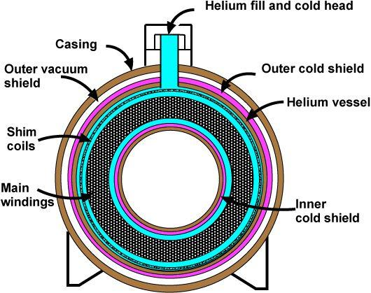
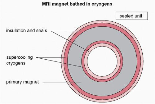
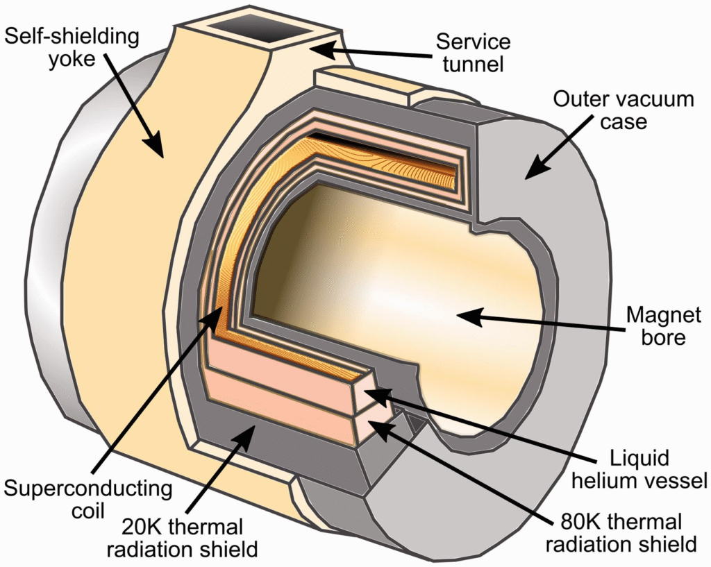
The MRI cryostat is a highly engineered vacuum-insulated vessel consisting of several concentric layers:
- Outer vacuum vessel
- Thermal radiation shield
- Multilayer insulation
- Liquid helium reservoir
- Superconducting magnet coils
- Cryocooler cold head
Each layer serves a distinct thermal function, collectively minimizing heat leakage into the superconducting region.
3. Overview of the SVU Real-Time Monitoring System
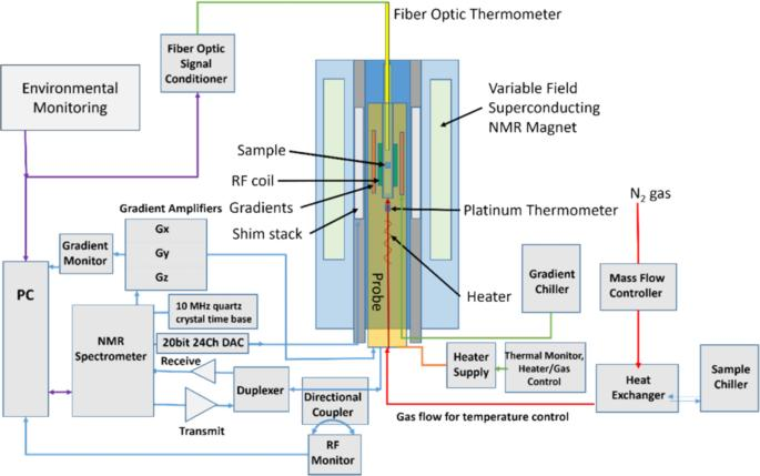
The Superconducting Vacuum Unit (SVU) serves as the central monitoring platform for the MRI magnet’s cryogenic environment. It continuously acquires data from multiple sensors distributed throughout the cryostat and associated refrigeration systems.
Its primary objectives include:
- Continuous monitoring of cryogenic conditions
- Detection of abnormal operating trends
- Generation of alarms
- Support for preventive maintenance
- Protection of the superconducting magnet
The monitoring interface typically displays:
| Parameter | Purpose |
|---|---|
| Magnetic Field | Confirms magnet energization |
| Helium Level | Indicates available cryogen |
| Thermal Shield Temperature | Measures thermal insulation efficiency |
| Cold Head Temperature | Monitors cryocooler performance |
| Magnet Pressure | Evaluates helium vapor pressure |
| Heater Status | Indicates pressure regulation activity |
| Diagnostic Indicators | Verify subsystem integrity |
Rather than interpreting any parameter in isolation, engineers evaluate all displayed values together to assess the overall health of the MRI magnet.
4. Understanding the Magnetic Field Status (Magnetic Field: ON)
The displayed parameter:
Magnetic Field: ON
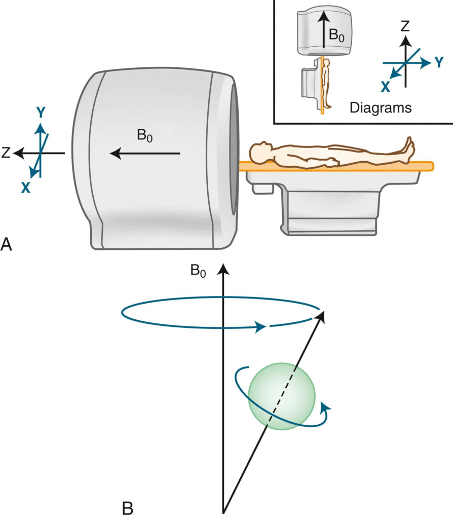
indicates that the superconducting magnet is actively generating its designed static magnetic field (B₀).
The B₀ field is the fundamental component of MRI imaging. It aligns hydrogen nuclei within the patient’s body, enabling radiofrequency pulses to produce measurable magnetic resonance signals.
Unlike conventional electromagnets that require continuous electrical power, superconducting MRI magnets operate in persistent mode, where electrical current circulates indefinitely through superconducting coils.
An ON status confirms that:
- Superconductivity is maintained.
- Persistent current remains stable.
- The cryogenic system is functioning correctly.
- Imaging can proceed normally.
Conversely, if a quench occurs—a rapid loss of superconductivity—the circulating current encounters electrical resistance, generating heat and causing the liquid helium to boil rapidly. The magnetic field collapses, and the system becomes unavailable for imaging until extensive service procedures are completed.
For biomedical engineers, the magnetic field status is a primary indicator of overall magnet functionality and is closely monitored alongside cryogenic parameters.
5. Understanding Helium Level (Helium Level: 80.6%)
The displayed value:
Helium Level: 80.6%
represents the percentage of liquid helium remaining inside the cryostat relative to its calibrated full capacity.
Liquid helium is the principal cryogen responsible for maintaining the superconducting coils near 4 Kelvin. Although modern cryocoolers significantly reduce helium loss, a small amount of evaporation—known as boil-off—still occurs due to unavoidable environmental heat leakage.
An 80.6% helium level is generally considered healthy for most modern MRI systems, although acceptable operating limits vary by manufacturer and scanner design.
Helium levels are influenced by:
- Natural boil-off
- Cryocooler efficiency
- Thermal shield performance
- Magnet pressure regulation
- Maintenance activities
- Unexpected thermal loads
If helium levels continue to decline unchecked, several risks emerge:
- Reduced cooling reserve
- Increased susceptibility to thermal disturbances
- Greater likelihood of magnet quench
- Potential interruption of clinical operations
To conserve helium, modern MRI systems employ:
- Two-stage cryocoolers
- High-vacuum insulation
- Reflective multilayer insulation
- Optimized pressure management
Routine helium level trending enables engineers to detect abnormal losses long before critical thresholds are reached.
6. Understanding Thermal Shield Temperature (58.2 K)
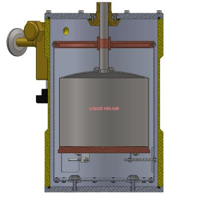
The thermal shield is an intermediate cooling barrier positioned between the room-temperature vacuum vessel and the 4 K helium reservoir. Its primary function is to intercept incoming heat before it reaches the liquid helium.
A displayed temperature of 58.2 K indicates the shield is operating within the typical range for many modern MRI systems, though acceptable values vary by manufacturer and cryostat design.
Heat reaches the cryostat through three mechanisms:
- Conduction through structural supports and cables.
- Convection, which is largely eliminated by the vacuum insulation.
- Thermal radiation emitted by warmer surfaces.
By maintaining the thermal shield at tens of Kelvin rather than room temperature, the cryocooler dramatically reduces the heat load on the helium reservoir. This improves cryogenic efficiency and minimizes helium boil-off.
An increasing thermal shield temperature may indicate reduced cryocooler performance, degradation of vacuum insulation, or excessive thermal loading. Monitoring long-term trends is therefore more informative than relying on a single reading.
7. Understanding C/H 2nd Stage Temperature (4.0 K)
The parameter:
C/H 2nd Stage Temperature: 4.0 K
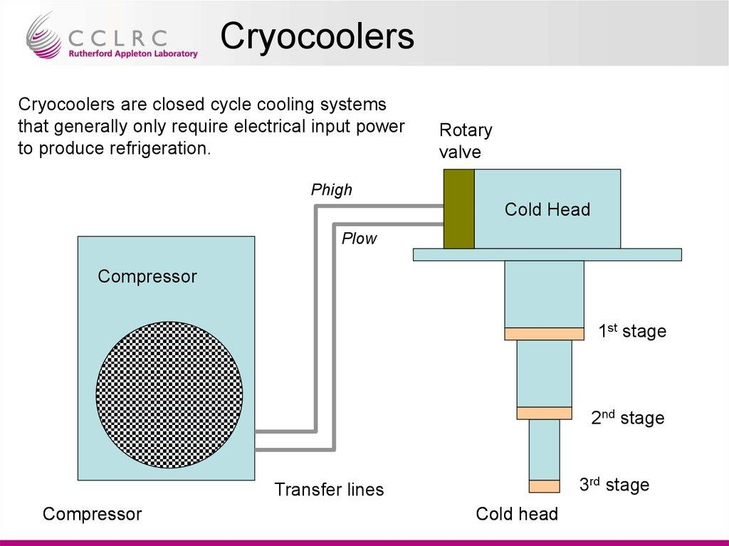
refers to the temperature of the second stage of the cryocooler cold head, which provides the ultra-low temperatures required to maintain superconductivity.
Modern MRI cryocoolers typically employ a two-stage refrigeration cycle. The first stage cools the thermal shield to approximately 40–80 K, while the second stage reaches around 4 K, directly supporting the helium reservoir.
Maintaining this temperature is critical because even small increases can accelerate helium evaporation and reduce the superconducting safety margin.
Biomedical engineers monitor this parameter closely because it serves as a direct indicator of cryocooler health. A gradual increase over weeks or months may suggest declining refrigeration efficiency, contamination, mechanical wear, or the need for scheduled maintenance.
Stable operation near 4 K indicates that the cryogenic system is effectively preserving the superconducting state and minimizing helium consumption.
8. Summary Table of Monitoring Parameters
| Parameter | Example Value | Engineering Interpretation |
|---|---|---|
| Magnetic Field | ON | Magnet is energized and superconducting |
| Helium Level | 80.6% | Healthy cryogen inventory for normal operation |
| Thermal Shield Temperature | 58.2 K | Effective interception of environmental heat load |
| C/H 2nd Stage Temperature | 4.0 K | Cryocooler operating correctly and maintaining superconductivity |
10. Understanding Magnet Pressure (Magnet Pressure: 4778 Pa)
The parameter:
Magnet Pressure: 4778 Pa
represents the internal pressure of helium gas inside the MRI cryostat. Although liquid helium cools the superconducting coils, a small fraction continuously evaporates due to unavoidable heat leakage. This evaporation produces helium vapor, increasing the internal pressure above the liquid surface.
The cryostat is designed to operate within a controlled pressure range that balances helium conservation with system safety. Pressure sensors continuously transmit measurements to the SVU monitoring system, allowing engineers to detect abnormal conditions before they become critical.
A reading of 4778 Pa (approximately 4.8 kPa) is generally consistent with normal operation for many MRI systems, although the acceptable range depends on the manufacturer and magnet design.
Why Magnet Pressure Matters
Cryostat pressure directly influences:
- Helium boil-off rate
- Cooling efficiency
- Cryostat stability
- Safety valve operation
- Overall magnet reliability
Pressure Regulation
Modern MRI magnets regulate pressure using:
- Pressure sensors
- Relief valves
- Pressurization heaters
- Cryocoolers
- Automatic control electronics
The objective is to maintain a stable pressure while minimizing unnecessary helium loss.
High Pressure
Excessive pressure may result from:
- Increased heat load
- Cryocooler degradation
- Blocked vent lines
- Pressure control malfunction
Potential consequences include:
- Increased helium consumption
- Activation of relief valves
- Higher quench risk under severe conditions
Low Pressure
Pressure below the normal operating range may indicate:
- Helium leakage
- Sensor malfunction
- Pressure regulation faults
Therefore, pressure trends are often more informative than isolated measurements.
11. Understanding Pressurize Heater Power (Pressurize Heater Power: 0.00 W)
The Pressurize Heater Power indicates the electrical power delivered to the pressurization heater.
Example:
0.00 W
This means the heater is inactive.
Purpose of the Pressurization Heater
The pressurization heater gently warms a small quantity of liquid helium, generating helium gas when necessary to maintain adequate internal pressure.
Unlike heating systems used for temperature control, this heater exists solely to regulate cryostat pressure.
Its activation is controlled automatically by the magnet control unit.
Typical Operation
The heater activates only when:
- Pressure falls below the desired setpoint
- Additional helium vapor is required
- Stable pressure must be restored
Therefore, a reading of 0.00 W generally indicates that the cryostat pressure is already within the desired operating range.
Continuous heater operation would not normally be expected during routine MRI operation.
12. Understanding Pressurize Heater Status (Pressurize Heater: OFF)
The status
Pressurize Heater: OFF
simply confirms that the pressure regulation heater is currently inactive.
This usually indicates:
- Stable cryostat pressure
- No additional helium gas generation required
- Normal automatic pressure regulation
If the heater frequently cycles ON and OFF, engineers should correlate this behavior with pressure trends, cryocooler performance, and helium level to determine whether the system is responding appropriately or compensating for another issue.
13. Understanding BO Heater Status (BO Heater: OFF)
The abbreviation BO refers to Boil-Off.
Boil-off is the natural evaporation of liquid helium caused by unavoidable environmental heat entering the cryostat.
Although modern MRI systems are often described as zero boil-off, this term generally means that the cryocooler recondenses most evaporated helium under normal operating conditions rather than eliminating evaporation entirely.
The BO Heater is associated with controlled boil-off management and specific operational procedures. During routine scanning, the status is commonly:
OFF
which indicates that no intentional helium evaporation is being induced.
The heater may activate during:
- Certain maintenance procedures
- Pressure regulation sequences
- Manufacturer-specific service operations
An unexpected BO Heater activation during routine clinical operation should be investigated according to the manufacturer’s service documentation.
14. Understanding Diagnostic Status Indicators
Beyond cryogenic measurements, the SVU monitoring system continuously evaluates the integrity of electrical circuits and safety subsystems.
14.1 Power Supply Diagnosis: OK
This confirms that the electrical power supplying the SVU monitoring electronics is functioning normally.
Engineers monitor:
- Voltage stability
- Internal power conversion
- Electronic health
- Communication reliability
Power abnormalities can compromise monitoring accuracy even if the magnet itself remains operational.
14.2 ERDU Battery Diagnosis: OK
The Emergency Run Down Unit (ERDU) incorporates a backup battery to maintain essential monitoring and safety functions during power interruptions.
Battery diagnostics verify:
- Charge capacity
- Battery voltage
- Internal resistance
- Backup readiness
Reliable battery operation is critical for maintaining protective functions during unexpected electrical failures.
14.3 ERDU Switch Connection: OK
This parameter confirms that safety switching circuits are electrically intact.
The SVU continuously checks:
- Switch continuity
- Cable integrity
- Connector condition
An “OK” status indicates that the emergency switching network is functioning correctly.
14.4 ERDU Heater Connection: OK
This diagnostic verifies the electrical continuity of heater circuits associated with emergency cryogenic control.
Typical monitoring includes:
- Open-circuit detection
- Short-circuit detection
- Connector integrity
14.5 BO Heater Connection: OK
This confirms that the Boil-Off heater circuit is electrically healthy.
Although the heater may be OFF, the monitoring system continuously verifies that it would operate correctly if required.
14.6 Pressurize Heater Connection: OK
This diagnostic confirms:
- Proper wiring
- Acceptable electrical resistance
- Functional heater circuit
An “OK” indication provides confidence that automatic pressure regulation can operate whenever necessary.
14.7 Magnetic Field Sensor Connection: OK
The magnetic field sensor continuously verifies the presence and stability of the MRI’s static magnetic field.
Many systems employ Hall-effect-based magnetic sensors or other precision field-monitoring technologies.
The Hall effect occurs when a magnetic field causes charge carriers moving through a conductor to experience a force perpendicular to both the current and the magnetic field, generating a measurable voltage proportional to the field strength.
Reliable sensor connections ensure accurate monitoring of magnet status and early detection of abnormal conditions.
15. Interpreting Overall System Health
Experienced biomedical engineers never evaluate a single parameter in isolation. Instead, they assess trends and relationships among all monitored values.
For example:
| Observation | Interpretation |
|---|---|
| Stable helium + stable pressure + 4 K cold head | Healthy cryogenic system |
| Falling helium + rising shield temperature | Increasing thermal load |
| Rising pressure + cryocooler warming | Possible refrigeration issue |
| Heater cycling frequently | Pressure regulation should be investigated |
Trend analysis often provides earlier warning than threshold alarms, allowing preventive maintenance before clinical operation is affected.
16. Common Alarm Conditions and Troubleshooting
| Condition | Possible Causes | Risks | Typical Corrective Actions |
|---|---|---|---|
| Low helium level | Natural boil-off, leak | Loss of cooling margin | Verify trend, inspect for leaks, schedule helium refill if required |
| High thermal shield temperature | Cryocooler degradation, vacuum deterioration | Increased helium consumption | Inspect cryocooler performance and vacuum integrity |
| High magnet pressure | Excess heat load, blocked vent, control malfunction | Relief valve activation, helium loss | Verify pressure regulation system |
| Cryocooler malfunction | Mechanical wear, compressor fault | Rising temperatures | Service cryocooler according to manufacturer recommendations |
| Sensor failure | Damaged cable, connector, electronics | Incorrect monitoring | Inspect wiring and replace faulty sensor |
| Power supply fault | Electrical failure | Loss of monitoring | Restore power and verify backup systems |
17. Biomedical Engineering Perspective
Routine monitoring of superconducting MRI magnets is a core responsibility of biomedical and MRI service engineers.
Typical responsibilities include:
- Reviewing SVU parameters daily
- Identifying abnormal trends
- Supporting preventive maintenance
- Assisting during helium refill procedures
- Performing acceptance testing after installation
- Coordinating cryocooler servicing
- Ensuring compliance with safety protocols
- Maintaining documentation and maintenance records
A proactive maintenance strategy minimizes downtime, reduces helium consumption, and extends magnet lifespan.
18. Key Takeaways
- Magnetic Field: ON confirms the superconducting magnet is energized.
- Helium Level reflects the available cryogenic reserve.
- Thermal Shield Temperature indicates insulation performance and heat interception.
- C/H 2nd Stage Temperature evaluates cryocooler efficiency in maintaining approximately 4 K.
- Magnet Pressure reflects helium vapor equilibrium within the cryostat.
- Pressurize Heater Power and Status indicate whether active pressure regulation is required.
- BO Heater Status relates to controlled helium boil-off management.
- Diagnostic indicators verify the integrity of electrical circuits, sensors, heaters, and safety systems.
- Engineers should interpret all parameters collectively rather than relying on a single value.
20. References
- Brown, R. W., Cheng, Y. N., Haacke, E. M., Thompson, M. R., & Venkatesan, R. (2014). Magnetic Resonance Imaging: Physical Principles and Sequence Design (2nd ed.). Wiley. https://www.wiley.com/
- Westbrook, C., Roth, C. K., & Talbot, J. (2018). MRI in Practice (5th ed.). Wiley-Blackwell. https://www.wiley.com/
- Bushberg, J. T., et al. (2020). The Essential Physics of Medical Imaging (4th ed.). Lippincott Williams & Wilkins. https://shop.lww.com/
- IAEA. Quality Assurance Programme for MRI Systems. https://www.iaea.org/
- IAEA Human Health Series publications. https://www.iaea.org/publications
- AAPM MRI Safety Resources. https://www.aapm.org/
- NCBI Bookshelf: Magnetic Resonance Imaging Physics. https://www.ncbi.nlm.nih.gov/books/
- IEC 60601-2-33: Medical Electrical Equipment – Particular Requirements for Magnetic Resonance Equipment for Medical Diagnosis. https://webstore.iec.ch/
- Siemens Healthineers – Magnet Technology. https://www.siemens-healthineers.com/
- GE HealthCare – MRI Technology. https://www.gehealthcare.com/
- Philips Healthcare – MRI Systems. https://www.philips.com/healthcare
- Wilson, M. N. (1983). Superconducting Magnets. Oxford University Press.
- Barron, R. F. (1985). Cryogenic Systems (2nd ed.). Oxford University Press.
- Van Sciver, S. W. (2012). Helium Cryogenics (2nd ed.). Springer. https://link.springer.com/
- Shellock, F. G. MRI Safety. https://www.mrisafety.com/
This two-part guide provides a practical yet scientifically grounded overview of MRI superconducting magnet monitoring, helping biomedical engineers, MRI service engineers, and students confidently interpret SVU real-time monitoring parameters while appreciating the underlying cryogenic and superconducting principles.