Anatomical Coordinate Systems for Medical Imaging and Biomechanics: Biomedical fundamentals
Anatomical Coordinate Systems for Medical Imaging and Biomechanics: Engineering Perspectives
Table of Contents
- Introduction: Why Anatomical Coordinate Systems Matter
- The Anatomical Position: The Global Reference Frame
- Body Planes: Standard Sections of the Human Body
- Sagittal Plane
- Frontal (Coronal) Plane
- Transverse (Horizontal) Plane
- Directional Terms: Describing Relative Location
- Anatomical Axes and Human Motion
- Applications in Medical Imaging
- Applications in Biomechanics and Motion Analysis
- Common Errors and Best Practices
- Engineering Takeaways
- References
1. Introduction: Why Anatomical Coordinate Systems Matter
In biomedical engineering, everything measured, modeled, or manipulated in the human body requires a coordinate system. Anatomical reference systems provide this framework.
- They define spatial orientation for organs, tissues, and sensors
- Standardize motion and imaging measurements across subjects
- Ensure repeatable and interpretable results for device design, signal acquisition, and biomechanical modeling
Key engineering insight:
Anatomical reference systems act as the Cartesian coordinates of the human body, aligning biology with engineering analysis.
2. The Anatomical Position: The Global Reference Frame
Definition
The anatomical position is the baseline posture from which all anatomical directions and planes are defined:
- Body upright, facing forward
- Arms at sides, palms forward
- Feet together, flat and pointing forward
Engineering Interpretation
| Concept | Anatomical Equivalent |
|---|---|
| Zero-load configuration | Anatomical position |
| Global reference frame | Standard anatomical orientation |
| Calibration pose | Baseline anatomical posture |
Relevance for Engineers
- Serves as reference for joint angles in motion capture
- Aligns prosthetic devices and exoskeletons
- Standardizes image orientation across CT, MRI, and ultrasound
- Provides baseline for biomechanical modeling
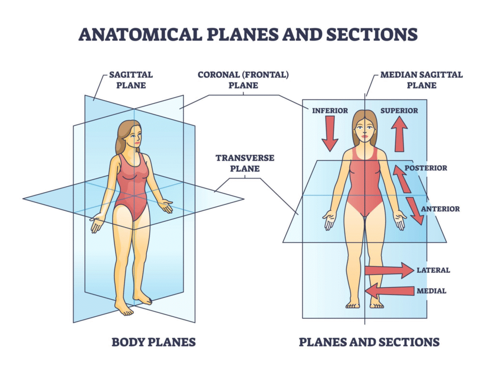
3. Body Planes: Standard Sections of the Human Body
Body planes divide the body into predictable sections, similar to engineering coordinate planes.
| Plane | Division | Engineering Analogy | Applications |
|---|---|---|---|
| Sagittal | Left / Right | Y–Z plane | Flexion/extension, gait analysis |
| Frontal (Coronal) | Front / Back | X–Z plane | Abduction/adduction, postural control |
| Transverse (Horizontal) | Top / Bottom | X–Y plane | Rotational motion, imaging slices |
3.1 Sagittal Plane
- Midsagittal: equal halves
- Parasagittal: unequal halves
- Engineering use: Flexion/extension analysis, left-right asymmetry detection
3.2 Frontal Plane
- Divides anterior vs posterior
- Engineering use: Lateral movement assessment, balance studies, EMG lateralization
3.3 Transverse Plane
- Divides superior vs inferior
- Engineering use: Cross-sectional imaging, rotational biomechanics, MRI/CT slice orientation
4. Directional Terms: Describing Relative Location
Directional terms define vector relationships between anatomical structures. They are analogous to axes descriptors in engineering systems.
| Term | Meaning | Engineering Use Case |
|---|---|---|
| Superior / Inferior | Toward head / feet | Device positioning |
| Anterior / Posterior | Front / back | Imaging orientation |
| Medial / Lateral | Toward / away from midline | Sensor placement, motion analysis |
| Proximal / Distal | Closer / farther from origin | Limb mechanics, prosthetic alignment |
| Superficial / Deep | Near surface / internal | Electrode depth, ultrasound imaging |
Engineering insight: These terms directly map to coordinate directions and vector fields in simulations and device design.
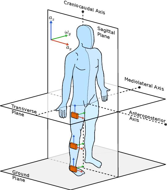
5. Anatomical Axes and Human Motion
Motion occurs around axes perpendicular to planes:
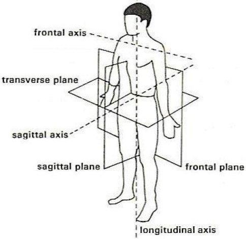
| Axis | Plane | Typical Motion | Engineering Relevance |
|---|---|---|---|
| Mediolateral | Sagittal | Flexion/extension | Joint angle tracking, robotic limbs |
| Anteroposterior | Frontal | Abduction/adduction | IMU alignment, kinematic modeling |
| Longitudinal | Transverse | Rotation | Rotation analysis, exoskeleton control |
Understanding axes is critical for biomechanics, robotics, and motion sensor interpretation.
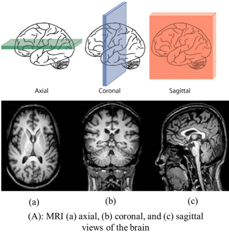
6. Applications in Medical Imaging
Anatomical reference systems are embedded in all imaging modalities:
- MRI, CT, Ultrasound: Planes define slice orientation
- DICOM standards: Images are annotated relative to anatomical axes
- Image registration: Aligning multiple scans requires reference to global anatomical axes
Example: A transverse CT slice can be computationally re-sliced into sagittal or frontal planes, preserving spatial relationships for device planning or analysis.
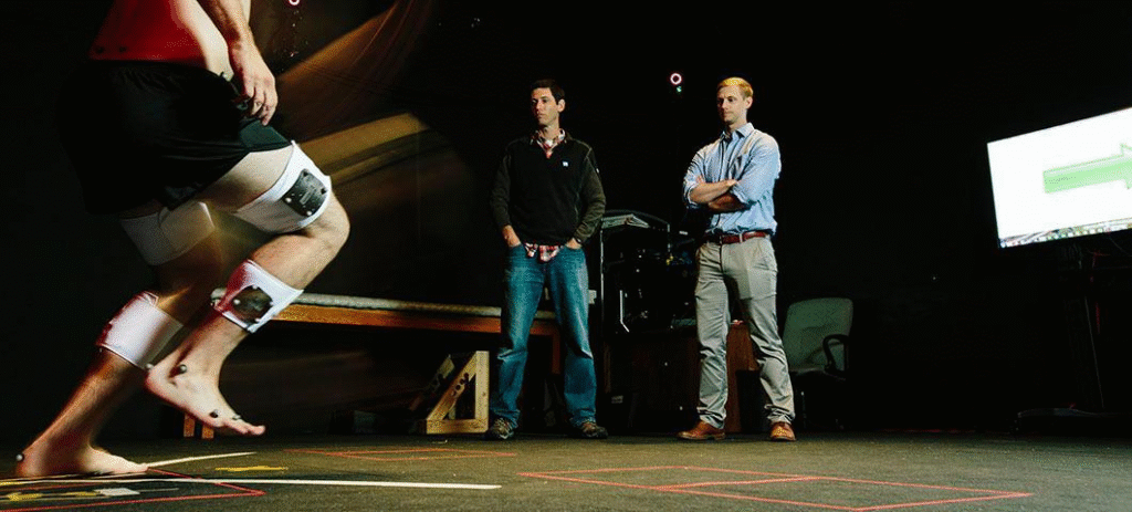
7. Applications in Biomechanics and Motion Analysis
- Motion capture systems rely on anatomical landmarks relative to reference frames
- Force plates and IMUs require consistent coordinate mapping
- Prosthetics, exoskeletons, and rehabilitation devices are calibrated relative to anatomical axes
Example: Knee flexion angles are calculated relative to the mediolateral axis in the sagittal plane.
8. Common Errors and Best Practices
| Error | Impact | Mitigation |
|---|---|---|
| Mislabeling left/right or anterior/posterior | Invalid analysis | Standardize anatomical position |
| Ignoring planes/axes | Confused motion or imaging interpretation | Map data to anatomical planes |
| Inconsistent reference frames | Non-comparable measurements | Use standardized anatomical coordinate systems |
Rule of thumb: Always define a global reference frame before measurement or modeling.
9. Engineering Takeaways
- Anatomical reference systems are foundational for signal acquisition, device interface, and modeling
- Every imaging, motion analysis, or device calibration task depends on a standardized spatial framework
- Engineers must internalize planes, axes, and directional terms as coordinate descriptors, not just biological vocabulary
12. References
- Moore, K. L., Dalley, A. F., & Agur, A. M. R. Clinically Oriented Anatomy. Lippincott Williams & Wilkins.
- Tortora, G. J., & Derrickson, B. H. Principles of Anatomy and Physiology. Wiley.
- Winter, D. A. Biomechanics and Motor Control of Human Movement. Wiley.
- Pohl, M., & Leach, J. Medical Imaging Signals and Systems. Academic Press.
- Enderle, J. D., Bronzino, J. D., & Blanchard, S. M. Introduction to Biomedical Engineering. Academic Press.