What Is a Cardiac Pacemaker? Components, Working Principle, Types, and Biomedical Engineering Guide
What Is a Cardiac Pacemaker? Components, Working Principle, Types, and Biomedical Engineering Guide
A practical, numbers-first guide for biomedical engineers — physiology, architecture, implantation, QA/testing, maintenance, and where the technology is heading, built on verified 2024–2026 literature.
Quick answer
A cardiac pacemaker is an active implantable electronic device that delivers timed, low-energy electrical pulses to the heart muscle to keep the heart rate from dropping too low (bradycardia) or to restore coordinated timing between the atria and ventricles when the heart’s own electrical system can’t. It is, in engineering terms, a battery-powered, hermetically sealed embedded controller running a closed-loop sense→decide→stimulate algorithm, connected to the heart either by insulated wire leads (transvenous) or, in newer designs, packaged entirely inside a capsule fixed directly to the heart wall (leadless).
Everything below unpacks that definition layer by layer — starting from why the heart needs a pacemaker at all, through to how one is built, implanted, tested, maintained, and where the field is going next.
Table of contents
- 1. Why the heart needs an artificial pacemaker
- 2. Working principle: the pacemaker as a control loop
- 3. Device architecture and components
- 4. Classification: the NBG/AAMI pacing code
- 5. Sensing, timing, and rate-adaptive algorithms
- 6. Implantation procedure
- 7. Biomaterials and power sources
- 8. Quality assurance and follow-up testing
- 9. Complications: acute and chronic, with real numbers
- 10. Maintenance, troubleshooting, and common failure modes
- 11. MRI conditionality and electromagnetic compatibility
- 12. Regulatory and standards framework
- 13. Manufacturer landscape (representative, non-exhaustive)
- 14. Future directions
- Conclusion
- FAQ
- References
1. Why the heart needs an artificial pacemaker
The heart has its own built-in “pacemaker cells.” A small cluster of specialized cells in the right atrium, the sinoatrial (SA) node, spontaneously depolarizes 60–100 times per minute. It does this using an ion channel family called HCN channels (hyperpolarization-activated, cyclic-nucleotide-gated channels) — think of them as channels that slowly leak a small inward current even at rest, which is exactly what lets a cell trigger its own next heartbeat without any external signal. The dominant subtype in the SA node is HCN4.
From the SA node, the electrical impulse spreads across the atria, is deliberately delayed by about 100–150 ms at the AV node (this delay is what gives the ventricles time to fill with blood before they contract), and then races down the His bundle and Purkinje fibers to make both ventricles contract together.
A pacemaker becomes medically necessary when this chain breaks:
– Sinus node dysfunction — the SA node fires too slowly or not at all.
– AV block — the electrical signal from the atria doesn’t reliably reach the ventricles.
– Infranodal / bundle-branch disease — the signal reaches the ventricles late or not in a coordinated way.
In every case, the engineering task is the same: replace a biological, self-timing, self-adapting oscillator with an electronic one that senses what the heart is already doing and only adds a pulse when the heart fails to act on its own.
2. Working principle: the pacemaker as a control loop
Strip away the medical terminology and a pacemaker is a real-time embedded control system with three stages, looped continuously:
1. Sense — an amplifier front-end reads the intracardiac electrogram (the local voltage signal picked up at the electrode, typically a few millivolts) and compares it against a programmable sensitivity threshold to decide “did the heart just beat on its own?”
2. Decide — a timing algorithm (implemented on a low-power microcontroller) checks that signal against programmed intervals: if no intrinsic beat is sensed within the expected window, the device schedules a pacing pulse; if a beat is sensed, the pulse is inhibited (this is the “demand” behavior every modern pacemaker uses — it never paces over a heartbeat that already happened on its own).
3. Stimulate — if a pulse is needed, an output capacitor discharges a brief, calibrated current pulse through the electrode into the myocardium, depolarizing the local tissue and triggering a contraction that then propagates through the heart just like a natural beat.
This is why the very first engineering question about any pacemaker is what does it pace, what does it sense, and how does it respond — which is exactly what the NBG code in Section 4 encodes.
3. Device architecture and components
3.1 Transvenous (lead-based) systems — the conventional architecture
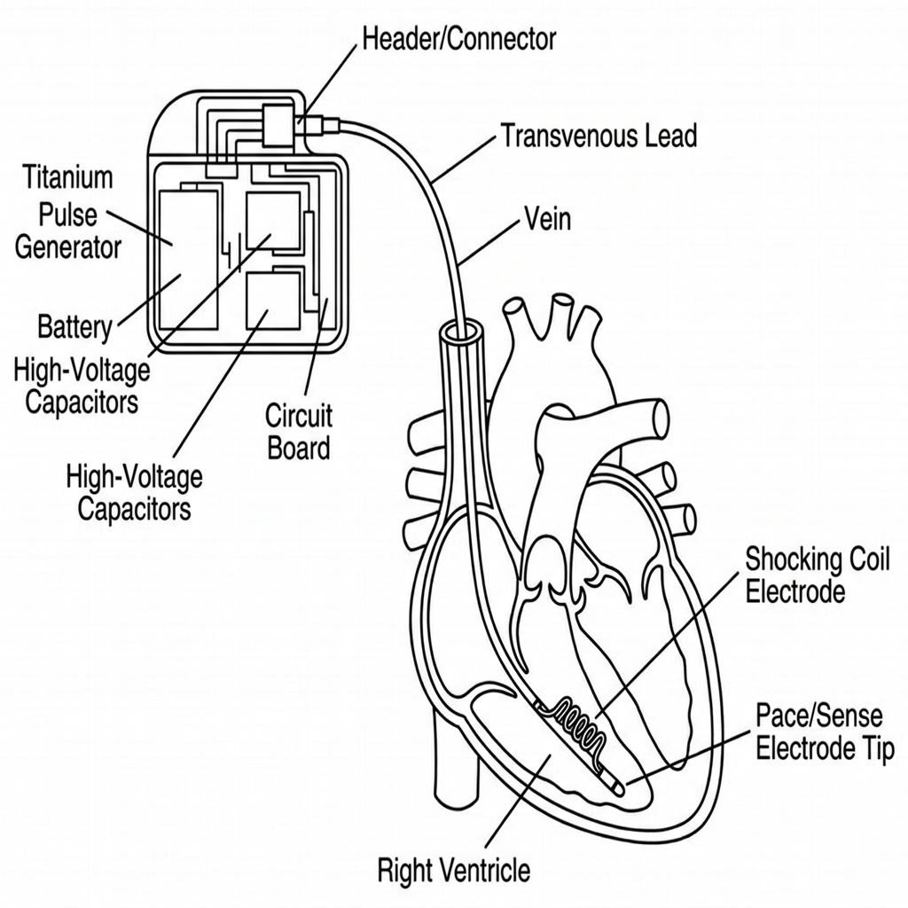
A conventional pacemaker system has three physically distinct parts, shown below:
Implantable pulse generator (IPG). This is “the pacemaker” as most people picture it: a hermetically sealed titanium can, roughly 40–50 cm³ and 20–30 g, implanted in a subcutaneous pocket, usually below the left or right collarbone. Inside: the battery, an output (high-voltage) capacitor, and a hybrid analog/digital circuit that runs sensing, timing, telemetry, and diagnostics.
Leads. Insulated, flexible conductors that carry the pacing pulse from the IPG to the heart and carry the sensed electrogram back. A lead is:
– Bipolar (two conductors, tip + ring electrode close together) — the modern default because the short sensing distance rejects far-field noise (skeletal muscle, other electronics) far better than unipolar.
– Unipolar (one conductor in the lead, the IPG can itself act as the return electrode) — largely legacy, still occasionally chosen for a thinner, more fracture-resistant lead body.
– Fixed to the endocardium either actively (a small screw-in helix at the tip) or passively (tines that lodge in the trabeculae of the right ventricle).
Electrodes. The actual metal-to-tissue interface, usually platinum–iridium or iridium-oxide-coated platinum for corrosion resistance and low polarization impedance, often with a steroid-eluting collar that slowly releases an anti-inflammatory (typically dexamethasone) to blunt the fibrotic scar that would otherwise raise the pacing threshold over the following weeks.
3.2 Leadless systems — the newer architecture
A leadless pacemaker (LP) collapses the entire IPG-lead-electrode chain into one small capsule that is delivered by catheter and fixed directly inside a heart chamber — no subcutaneous pocket, no transvenous lead at all. The two commercially established platforms are Medtronic’s Micra family (single-chamber, ventricular only) and Abbott’s AVEIR DR, the first dual-chamber leadless system, which pairs an atrial capsule (~2.4 g) with a ventricular capsule (~3.5 g) and keeps them synchronized without any physical wire between them — instead, the two capsules talk to each other wirelessly. The diagram below puts the two architectures side by side:
How the two capsules stay coordinated — and why the radio band matters. AVEIR DR’s atrial and ventricular capsules exchange short data packets over a wireless link in the 902–928 MHz ISM band — the “Industrial, Scientific, and Medical” band, a slice of unlicensed radio spectrum also used by things like RFID readers and some cordless devices, chosen because equipment operating there doesn’t need per-device licensing and interferes predictably. Because the two capsules sit only a few centimeters apart inside the same heart, the link doesn’t need much range or bandwidth — it just needs to be fast and reliable enough that when the atrial capsule senses (or paces) a beat, the ventricular capsule hears about it in time to time its own pulse correctly. That timing budget is why communication latency — the delay between the atrial event happening and the ventricular capsule receiving word of it — is a first-order design parameter here: too much latency and the AV delay the device is trying to reproduce becomes inaccurate; too much packet loss and the ventricular capsule has to fall back to pacing on its own internal timer without atrial information for that beat. Early commercial data reports a 98.8% link success rate, with the remaining beats handled by fallback (asynchronous) timing.12
4. Classification: the NBG/AAMI pacing code
Every pacemaker’s function is described by the standardized NBG code (NASPE/BPEG Generic code, adopted by AAMI — the letters just stand for the professional societies that wrote it), using up to five positions:
| Position | What it describes | Possible letters |
|---|---|---|
| I | Chamber(s) paced | O = none, A = atrium, V = ventricle, D = dual (both) |
| II | Chamber(s) sensed | O, A, V, D |
| III | Response to a sensed beat | O = none, I = inhibited (withhold pulse), T = triggered (fire immediately), D = dual |
| IV | Rate modulation | O = fixed rate, R = rate-responsive (adapts to activity) |
| V | Multisite pacing | O, A, V, D |
In plain terms: position I is “where it can zap,” position II is “where it can listen,” position III is “what it does when it hears a natural beat,” and position IV is “does it speed up when you exercise.” Reading off a mode like DDD(R) left to right: it can pace both chambers, sense both chambers, both inhibit and trigger depending on what it senses, and — if the R is present — speed up during activity.
The three modes an engineer will meet constantly in practice:
| Mode | Meaning | Typical indication |
|---|---|---|
| VVI(R) | Paces & senses ventricle only; inhibited by a sensed beat; rate-adaptive if R | Permanent atrial fibrillation with slow ventricular rate — no point pacing an atrium that’s fibrillating |
| AAI(R) | Paces & senses atrium only | Isolated sinus node dysfunction with a healthy, intact AV node |
| DDD(R) | Paces & senses both chambers, full dual response | AV block, or sinus node disease with any risk of AV block — the physiologic, AV-synchrony-preserving default for two-lead systems |
5. Sensing, timing, and rate-adaptive algorithms
Sensitivity. The amplifier’s detection threshold is programmable — typically 0.25–2.0 mV on the atrial channel and 1.5–5.0 mV on the ventricular channel. Set it too sensitive and the device picks up noise (muscle activity, electromagnetic interference) and mistakes it for a heartbeat — a fault called oversensing, which can wrongly inhibit a needed pulse. Set it too insensitive and a real, weak heartbeat goes undetected — undersensing — and the device paces unnecessarily on top of a beat that already happened.
Refractory and blanking periods. After every sensed or paced event, the device deliberately “goes deaf” on that channel for a short programmed window (roughly 150–400 ms) so it doesn’t re-trigger on the tail of the same electrical event, or pick up the other chamber’s signal bleeding across (crosstalk) and the far-field of a ventricular contraction being misread by the atrial channel (far-field R-wave oversensing).
Rate-adaptive (R) pacing. An accelerometer (body motion) or, in some models, a minute-ventilation sensor (via transthoracic impedance) estimates physical exertion and raises the paced rate accordingly, mimicking the SA node’s natural response to exercise.
Dual-chamber leadless coordination. As discussed in §3.2, when the “device” is really two independent capsules, AV synchrony depends on wireless telemetry rather than a shared internal clock — a genuinely different control-systems problem from a single-IPG two-lead system, and one where packet latency and loss-handling logic are now part of the pacing algorithm itself, not just the communications stack.1
6. Implantation procedure
Transvenous implantation is a catheter-lab procedure done under local anesthesia with conscious sedation, typically 45–90 minutes for a dual-chamber system:
1. Venous access. The subclavian, axillary, or cephalic vein is punctured (axillary access, under ultrasound guidance, is increasingly preferred over subclavian because it avoids the “subclavian crush” risk of lead compression between the clavicle and first rib).9
2. Pocket creation. A subcutaneous (or sub-pectoral) pocket is dissected to house the IPG, sized to the generator’s footprint.
3. Lead positioning. Under fluoroscopic (X-ray) guidance, the lead is advanced through the vein, across the tricuspid valve if going to the ventricle, and fixed at the target site — typically the right ventricular apex or septum, and the right atrial appendage or septum for the atrial lead.
4. Electrical testing (acute measurements). Before anything is secured permanently, the implanting team measures — with the pacing system analyzer or the permanent programmer — the same three parameters that will be checked at every follow-up for the life of the device: capture threshold, sensing amplitude, and lead impedance (all defined in §8). Acceptable acute targets are typically capture threshold ≤ 1.0 V at a 0.4–0.5 ms pulse width, sensing ≥ 5 mV (ventricle) / ≥ 1.5 mV (atrium), and impedance in the 300–1000 Ω range — outside that band the lead is repositioned before proceeding.10
5. Generator connection and programming. The lead(s) are plugged into the header of the IPG, the generator is placed in the pocket, and initial parameters (mode, rates, outputs, sensitivities) are programmed via a wireless programmer head/wand.
6. Pocket closure. The pocket is closed in layers; the patient is monitored (chest X-ray to confirm lead position and rule out pneumothorax, plus device interrogation) before discharge, usually the same day or next morning.
Leadless implantation replaces steps 1–2 and 6 with a single femoral-vein catheter delivery of the capsule directly to the endocardium, and step 5 is performed capsule-side rather than through a separate generator — which is precisely why it removes the pocket- and lead-specific complication categories discussed in §9.
7. Biomaterials and power sources
7.1 Battery chemistry — the numbers that matter
| Chemistry | Voltage behavior | Typical capacity | Typical longevity | Trade-off |
|---|---|---|---|---|
| Lithium–iodine (Li–I₂) | Flat ~2.8 V plateau, then drops | ~1–2 Ah | 8–12 years | Flat curve makes remaining-life prediction harder near end-of-life |
| Lithium–carbon monofluoride (Li–CFx) | Starts ~3.0 V, declines gradually | ~2–3 Ah | 10–15 years | More predictable depletion curve; now the dominant modern chemistry |
| Hybrid Li–CFx/SVO (used in devices that also need high-current pulses) | Combines high-capacity CFx with high-rate silver vanadium oxide | Application-dependent | Comparable | Mainly relevant where a device also has to deliver a high-voltage shock (ICDs); pure pacemakers rarely need this |
Real device longevity, published by manufacturers under the same accelerated-battery-discharge test conditions (typically a fixed pacing amplitude, 0.4 ms pulse width, 60 pulses/min, at a defined pacing load such as 600 Ω), currently ranges from about 12–13 years for standard-size dual-chamber transvenous devices with good battery technology, up to 15.6–16.7 years projected for the latest single-chamber leadless capsules (Medtronic Micra AV2/VR2), which packed roughly 40% more battery capacity into the same footprint as their predecessor.11 In a dual-capsule leadless system, the two capsules deplete at different rates depending on how much each one paces, so end-of-life tracking and staged replacement planning have to be done per-capsule, not per-system.
7.2 What happens at end of battery life
Three programmer-reported states matter operationally:
– ERI (Elective Replacement Indicator): the battery has reached a voltage/impedance threshold that means roughly 3–6 months of safe function remain (device-specific — always confirm in that model’s manual). This is the trigger to schedule a generator replacement; it is not an emergency.
– EOS (End of Service, sometimes called EOL, End of Life): the point beyond ERI at which safety margin runs out — output may fall out of spec, or in some designs the device switches to a fixed, low-power backup safety mode. Explant/replacement at or before this point is not elective.
– EOL vs. EOS terminology: manufacturers are not fully consistent — some use EOL and EOS interchangeably, others distinguish them as sequential stages after ERI. Always check the specific device’s technical manual rather than assuming.
7.3 Electrode and lead materials
Platinum–iridium and iridium-oxide-coated electrodes remain standard for biocompatibility, corrosion resistance, and low polarization impedance. Lead insulation is silicone (flexible, historically prone to lipid-absorption-related degradation over a decade-plus) or polyurethane (stiffer, more cut-resistant, historically susceptible to environmental stress cracking in certain older formulations); newer co-polymer and PEEK-based insulations are being evaluated for improved long-term mechanical durability.
7.4 Emerging power concepts
Beyond primary batteries, recent materials-science literature (2025–2026) documents galvanic-cell-based self-powered bioelectronic devices, where the implant’s own electrodes double as a biocompatible galvanic cell, harvesting energy from the local tissue electrochemical environment rather than relying solely on a pre-charged battery. The same review is explicit that, for now, this remains an emerging concept with real translational risk still to resolve — infection risk, constraints on patient mobility, and in vivo device failure from material degradation or biofouling — so it is not yet a cardiac-pacing product.4 Piezoelectric harvesting from cardiac wall motion and inductive (coil-to-coil) wireless recharging are separate, also-still-early research directions aimed at the same goal: fewer lifetime replacement surgeries.3
8. Quality assurance and follow-up testing
QA for a pacemaker is not a one-time factory step — it is a recurring loop that runs from manufacturing through every outpatient follow-up for the device’s entire service life.
8.1 Manufacturing / acceptance-level QA
– Electrical safety testing to IEC 60601-1 (general requirements for basic safety and essential performance of medical electrical equipment) — leakage current, dielectric withstand, and output accuracy verification against the programmed setting.
– Output verification — confirming the delivered pulse amplitude and pulse width at the electrode terminals match the programmed values within specification across the rated battery voltage range.
– Hermeticity (helium leak) testing — the titanium can and its feedthroughs are checked with a helium mass-spectrometer leak detector to confirm the seal will keep body fluids out and battery chemistry contained for the device’s rated life; this is a standard aerospace/electronics hermetic-package technique carried directly into implantable device manufacturing.
– Environmental and mechanical qualification — vibration, thermal cycling, and biocompatibility testing (ISO 10993) on all tissue-contacting materials.
– Design/process validation against ISO 14708-2 (the implant-specific active implantable medical device standard for pacemakers — see §10) before the device can be released to clinical use.
8.2 Follow-up (in-service) QA — what the programmer checks at every visit
| Parameter | What it means | Typical acceptable range |
|---|---|---|
| Capture threshold | Minimum pulse amplitude that reliably triggers a heartbeat at a given pulse width | ≤ 1.0 V at 0.4–0.5 ms is a good target; programmed output is normally set at 2–3× this threshold as a safety margin |
| Sensing amplitude | Size of the intrinsic electrogram the lead picks up | Ventricular ≥ 5 mV; atrial ≥ 1.5–2 mV typical minimums for reliable sensing |
| Lead impedance | Electrical resistance of the complete pacing circuit (lead + tissue interface) | ~300–1000 Ω; a sudden large drop suggests insulation failure, a sudden large rise suggests a lead fracture or loose connection |
| Battery status / remaining voltage | Tracks toward ERI/EOS | Compared against the manufacturer’s discharge curve for that model |
Follow-up is typically done at 1–3 months post-implant, then every 6–12 months, shifting to every 3 months once the device reaches its “one-year-remaining” battery status — increasingly via remote monitoring (a bedside transmitter that automatically sends these same parameters to the clinic between in-person visits).
9. Complications: acute and chronic, with real numbers
The best current comparative data comes from a Medicare-linked, real-world Coverage-with-Evidence-Development (CED) study comparing Abbott’s AVEIR DR dual-chamber leadless system against dual-chamber transvenous pacemakers (759 leadless vs. 77,422 transvenous implants):1
| Outcome | Transvenous | Leadless (AVEIR DR) | Effect |
|---|---|---|---|
| 30-day overall complications | 9.2% | 7.9% | No significant difference |
| 30-day device-related complications | 3.9% | 2.0% | ~50% lower (p < 0.01) |
| 6-month device-related complications | 5.9% | 2.8% | ~52% lower (p < 0.01) |
| 6-month device reinterventions | 4.3% | 2.1% | ~51% lower (p < 0.01) |
| 6-month mortality (adjusted) | 5.6% | 6.6% | No significant difference |
| Acute cardiac perforation/effusion | 0.6% | 1.2% | Higher with leadless — see note below |
Why leadless removes some risks but not all. Because a leadless capsule has no subcutaneous pocket and no transvenous lead body, it structurally cannot suffer the two complication categories that have historically dominated transvenous pacemaker morbidity: pocket complications (hematoma, infection, skin erosion) and lead complications (fracture, insulation failure, dislodgement — about 1.7% acutely in transvenous systems). What it doesn’t remove is the risk from the fixation mechanism itself contacting the heart wall — active-fixation helix capsules carry a somewhat higher acute cardiac perforation/pericardial effusion signal, part of which is a real mechanical risk and part of which is simply better detection, since leadless implantation is routinely monitored by intracardiac echocardiography (ICE) that transvenous implantation does not typically use.15
Other complications that apply across both architectures: venous thromboembolism (~1.1–1.5%), device-related infection (~0.4–1.1%, higher in dialysis-dependent and immunosuppressed patients), and chronic threshold rise from fibrotic encapsulation of the electrode over the following weeks to months — substantially blunted by steroid-eluting tips.
10. Maintenance, troubleshooting, and common failure modes
“Maintenance” for an implanted pacemaker isn’t user-serviceable hardware upkeep — it is the combination of scheduled follow-up testing (§8.2), remote monitoring, and a defined troubleshooting decision tree when the device or the patient signals a problem.
| Failure mode | Typical electrical signature | Usual cause |
|---|---|---|
| Failure to capture | Pacing spike on ECG with no resulting heartbeat | Lead dislodgement, exit block (fibrosis raising the threshold above the programmed output), lead fracture, battery depletion |
| Failure to sense (undersensing) | Device paces even though the heart already beat on its own | Lead dislodgement, insulation failure, inadequate sensitivity setting, myocardial fibrosis reducing signal amplitude |
| Oversensing | Device inappropriately withholds a needed pulse | Lead fracture (“noise”), myopotential (skeletal muscle) sensing, electromagnetic interference, far-field crosstalk |
| Lead fracture | Sudden high or erratic impedance, intermittent noise | Mechanical stress at points of flexion (e.g., under the clavicle), material fatigue |
| Insulation failure | Sudden low impedance | Lipid absorption (silicone), stress cracking (some polyurethanes), abrasion against the can or another lead |
| Pacemaker syndrome | Not a device fault — a hemodynamic/symptomatic problem | Loss of AV synchrony (e.g., VVI pacing in a patient who needed dual-chamber support), causing atrial contraction against a closed AV valve |
| Battery depletion beyond ERI | Output or rate falls out of programmed spec, or device reverts to a fixed backup mode | Missed follow-up past ERI |
The engineering takeaway: nearly every one of these failure signatures maps directly back to one of the three follow-up parameters in §8.2 — impedance for lead integrity, sensing amplitude for detection reliability, and capture threshold for output adequacy — which is exactly why those three numbers, not a generic “is it working,” are what every programmer check and every remote-monitoring transmission is built around.
11. MRI conditionality and electromagnetic compatibility
MRI exposes a cardiac implantable electronic device (CIED) to three distinct physical hazards, each with a distinct engineering mitigation:
| MRI hazard | Mechanism | Design mitigation |
|---|---|---|
| RF heating | The lead can act as an antenna for the MRI’s RF pulses, concentrating heating at the electrode tip | Filtered/impedance-engineered lead conductors that dampen induced RF currents; shorter effective antenna length via bipolar design |
| Force/torque on the device | The static magnetic field can pull on or twist any ferromagnetic material in the device | Reduced-ferromagnetic-content (or fully non-ferromagnetic) housings and headers |
| Oversensing / inappropriate pacing | Rapidly switching gradient fields can be picked up by the sensing amplifier and misread as cardiac signal | A dedicated “MRI mode,” programmed before the scan, that switches to a fixed asynchronous pacing rate and disables rate-response sensors for the duration of the scan |
Current expert consensus (Society for Cardiovascular Magnetic Resonance, 2024) confirms MRI can be performed safely on the large majority of patients with a CIED — both MRI-conditional-labeled devices and many legacy non-conditional systems — provided the institution follows a standard protocol: pre-scan interrogation and reprogramming to MRI mode, physiological monitoring during the scan, and post-scan re-interrogation to confirm parameters returned to normal and no unexpected changes occurred.6 MRI-conditional labeling itself is field-strength- and body-region-specific (commonly validated at 1.5 T, increasingly at 3 T) and always device- and lead-combination-specific — a conditional generator paired with a non-conditional lead is not a conditional system.
12. Regulatory and standards framework
The two standards most directly relevant to a cardiac pacemaker, specifically, are:
– ISO 14708-2 — “Implants for surgery — Active implantable medical devices — Part 2: Cardiac pacemakers,” the implant-specific particular standard covering electrical, mechanical, and labeling requirements unique to pacemakers.
– ISO 14117 — “Active implantable medical devices — Electromagnetic compatibility — EMC test protocols for implantable cardiac pacemakers, implantable cardioverter defibrillators and cardiac resynchronization devices,” which defines how EMC immunity (to sources like electrosurgery, security gates, induction cooktops, and MRI-adjacent fields) is actually tested.
These sit under the general active-implant framework of ISO 14708-1, and the device as a whole electrical system is also subject to IEC 60601-1 general safety requirements. (Note: IEC 60601-2-24 is the particular standard for infusion pumps and controllers — a common mix-up, since it sits numerically next to the cardiac-device family of standards but does not apply to pacemakers.)
Regulatory pathway: in the U.S., FDA premarket approval for genuinely novel architectures (such as the first dual-chamber leadless system) is commonly paired with a mandatory CMS Coverage-with-Evidence-Development (CED) study — structured registry follow-up at 30 days, 6 months, and out to 2 years — before broad reimbursement and long-term safety/durability claims are considered fully established. In the EU, active implantable pacemakers fall under the EU Medical Device Regulation (MDR 2017/745) as Class III devices, the highest-scrutiny risk class.
13. Manufacturer landscape (representative, non-exhaustive)
| Manufacturer | Representative transvenous platform | Representative leadless platform | Notable numbers |
|---|---|---|---|
| Medtronic | Azure MRI SureScan | Micra AV2 / VR2 | Azure IPG ≈ 46.6 × 50.8 × 7.4 mm, ~22.5 g; Micra AV2/VR2 volume 0.8 cc, projected longevity ~15.6 / 16.7 years |
| Abbott | Assurity MRI | AVEIR DR (first dual-chamber leadless system) | AVEIR DR atrial capsule ~2.4 g, ventricular capsule ~3.5 g, i2i link 902–928 MHz |
| Boston Scientific | Accolade (ENDURALIFE battery platform) | — (leadless in development) | Accolade MRI EL battery capacity 1.6 Ah; real-world projected longevity up to ~12.8 years |
| Biotronik | Edora 8 | — | Edora 8 single-chamber variant projected longevity ~13 years despite reduced form factor |
These figures are manufacturer-published, tested under accelerated battery-discharge conditions at a defined pacing output, pulse width, rate, and lead impedance — always confirm the exact test conditions in the specific model’s technical manual before quoting a longevity number in a design or procurement context, since longevity is highly sensitive to how much a given patient’s device actually paces.
14. Future directions
Multi-functional and multi-site leadless platforms. Active engineering work targets triple-site leadless pacing (approaching biventricular resynchronization without any lead), and eventual convergence with leadless defibrillation and integrated hemodynamic/biochemical sensing (intracardiac pressure, temperature).
Next-generation power. Higher-energy-density battery chemistries, inductive wireless recharging, and biocompatible galvanic or enzymatic energy harvesting are active research directions aimed at extending service intervals and reducing lifetime replacement surgeries — still pre-clinical for pacing specifically as of this writing.34
Biological pacemakers. Gene- and cell-therapy approaches aim to give ordinary heart muscle cells the same spontaneous-firing property the SA node has, most often by forcing them to express HCN-family channels (HCN2/HCN4) or, in an earlier line of work, the transcription factor TBX18. The evidence here has genuinely shifted recently: HCN2/HCN4 overexpression continues to reliably generate pacemaker-like automaticity in animal models, while a 2025–2026 re-evaluation using adeno-associated virus (AAV) delivery of TBX18 found that, unlike AAV-HCN2, it did not reliably induce the pacemaker gene program or generate robust biological pacing — and at higher expression levels caused cardiac fibrosis instead. That is a meaningful correction to earlier, more optimistic reports about TBX18 specifically, and it means the field is currently converging back toward ion-channel-based (HCN) approaches rather than transcription-factor reprogramming.87 Clinical translation of any biological-pacemaker approach still awaits resolution of durability, immunogenicity, and regulatory classification (gene therapy vs. device) before large-scale human trials.
Conclusion
Strip away the acronyms and a cardiac pacemaker is still, at its core, a sense-decide-stimulate control loop wired to the heart’s own conduction hierarchy. What has changed is where that loop lives and how it talks to itself: leadless dual-chamber systems now run the loop across two independently powered, wirelessly-coordinated capsules instead of one generator and two wires — removing lead fracture and pocket infection as failure modes at the cost of a genuinely new communication-reliability problem. Materials science keeps nudging electrode impedance and insulation durability in a good direction, MRI has gone from “contraindicated” to “routine with a protocol,” and the QA loop that starts on the manufacturing line literally never stops — it just moves from a leak-test bench to a follow-up programmer for the next 10–17 years. The research frontier — energy harvesting, integrated biosensing, and biological pacemaking — is real but earlier-stage than press coverage sometimes suggests, and the TBX18 correction is a useful reminder to read the newest primary source rather than the most-cited one.
FAQ
What is the difference between a pacemaker and a defibrillator (ICD)? A pacemaker delivers low-energy pulses continuously as needed to prevent the heart rate from being too slow. An implantable cardioverter-defibrillator (ICD) is built to also deliver a high-energy shock to stop a life-threatening fast rhythm (ventricular fibrillation/tachycardia); most ICDs include full pacemaker functionality as well, but a standard pacemaker cannot defibrillate.
How long does a pacemaker battery last? Typically 8–15 years for transvenous systems and up to a projected 15–17 years for the newest single-chamber leadless capsules, depending heavily on how much the specific patient’s device actually paces (a patient who paces 100% of the time depletes the battery faster than one who paces occasionally).
Can someone with a pacemaker get an MRI? In the large majority of cases, yes — with a standard pre-scan interrogation/reprogramming protocol and post-scan follow-up, per current expert consensus, regardless of whether the device is formally “MRI-conditional” or an older non-conditional model, as long as the treating team follows the appropriate safety protocol.
What’s the difference between ERI, EOS, and EOL? ERI (Elective Replacement Indicator) means roughly 3–6 months of safe function remain and it’s time to schedule a replacement. EOS/EOL (End of Service / End of Life — terminology varies by manufacturer) is the later point where safety margin has run out and replacement is not elective. Always check the specific device’s manual, since the exact naming and thresholds are model-specific.
Are leadless pacemakers safer than traditional ones? Real-world comparative data shows roughly 50% fewer device-related complications and reinterventions with a dual-chamber leadless system than a transvenous one at 30 days and 6 months, mainly because pocket- and lead-specific complications are structurally impossible with a leadless design — but leadless systems show a slightly higher acute cardiac perforation/effusion signal, so “safer” depends on which complication category matters most for a given patient.
What is a biological pacemaker, and does it exist yet? It’s an experimental approach that uses gene or cell therapy to make ordinary heart cells generate their own spontaneous electrical activity, instead of implanting hardware. It works in animal models with HCN-channel-based approaches; it is not yet a clinical human therapy, and a 2025–2026 study found the alternative TBX18-based approach specifically does not work as previously reported.
References
-
Lo, M., et al. (2026). Leadless Versus Transvenous Dual-Chamber Pacemakers: Real-World Evidence From the AVEIR DR Coverage With Evidence Development Study. Journal of Cardiovascular Electrophysiology, 37(3):544–553. https://doi.org/10.1111/jce.70255 ↩↩↩↩
-
Hadadi, C.A., Lee, K.W., Lo, M., et al. (2025). Commercial Implant Experience of a Helix-Fixation Dual-Chamber Leadless Pacemaker. Journal of Cardiovascular Electrophysiology, 36(7):1559–1566. https://doi.org/10.1111/jce.16688 ↩
-
Haines, D.J., Nazir, M.H. (2026). Advancing Battery Technology for Wearable and Implantable Devices: The Current Challenges and Future Directions — A Short Review. Future Batteries, 9:100148. ↩↩
-
Xin, Y., et al. (2025). Galvanic-Cell-Based Self-Powered Bioelectronic Devices. Advanced Materials, 37(50):e2509169. https://doi.org/10.1002/adma.202509169 ↩↩
-
Awashra, A., et al. (2025). Cardiac Lead Perforation: Mechanisms, Detection, and Clinical Management. Circulation: Arrhythmia and Electrophysiology. ↩
-
Kim, D., et al. (2024). SCMR Expert Consensus Statement for Cardiovascular Magnetic Resonance of Patients With a Cardiac Implantable Electronic Device. Journal of Cardiovascular Magnetic Resonance. ↩
-
Farraha, M., et al. (2018). Gene Therapy Approaches to Biological Pacemakers. PMC, and subsequent HCN4/HCN2-based cardiac pacemaker-cell reprogramming literature (e.g., Lin, Z., et al. (2024). A New Paradigm for Generating High-Quality Cardiac Pacemaker Cells From Mouse Pluripotent Stem Cells. Signal Transduction and Targeted Therapy). ↩
-
Rivaud, M.R., et al. (2025). Adeno-Associated Virus (AAV)-TBX18 Does Not Generate Biological Pacemaker Activity, Unlike AAV-Hcn2. bioRxiv preprint. https://doi.org/10.1101/2025.09.11.672351 ↩
-
Puette, J.A., et al. (2024). Pacemaker Insertion. StatPearls, NCBI Bookshelf. ↩
-
Tan, J.L., et al. (2024). Acute Increase in Pacing Capture Threshold and Impedance After Implantation. IJC Heart & Vasculature. ↩
-
Leal, M.A., et al. (2025). Device Longevity of a Leadless Pacemaker Family. PMC; and Defaye, P., et al. (2025). Cardiac Implantable Electronic Devices’ Longevity. PMC. ↩